
|
k1.spdns.de / Develop / Hardware / K1-Computer / K1-CPU / ALU / |
 Overview
| Control Unit
| Microcode Header
| Arithmetic Unit
| Data Registers
| Address Registers
| Expansion Bus Overview
| Control Unit
| Microcode Header
| Arithmetic Unit
| Data Registers
| Address Registers
| Expansion Bus
|
|
|
k1.spdns.de / Develop / Hardware / K1-Computer / K1-CPU / ALU / |
| Overview
| Control Unit
| Microcode Header
| Arithmetic Unit
| Data Registers
| Address Registers
| Expansion Bus
|
Work-in-progress – I'm currently reworking the project pages!
Some text on this page is in German only.
It will be translated to English some time later.
Last updated: 2012-06-28
Questions & comments to Kio
 2009-08-16: After a long while I resumed work on the ALU. I wired a test circuit for the 3-resistor majority gate, which i use in the ALU for the joined AND and OR functions. Dieter Müller has written an article (website now offline) about the majority gate and it's use for ALU design.
I was worried when i realized that the control line, which selects between AND and OR, has to drive 16 resistors (for 16 bits). A quick calculation resulted in 24 mA worst-case load on this line with my choosen value of 2.2kΩ for the resistors. On the other hand, 2.2kΩ might be too high and thus the propagation delay too long. So i was already thinking of what to do when the tests failed.
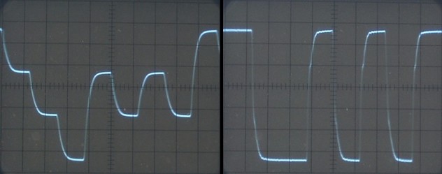
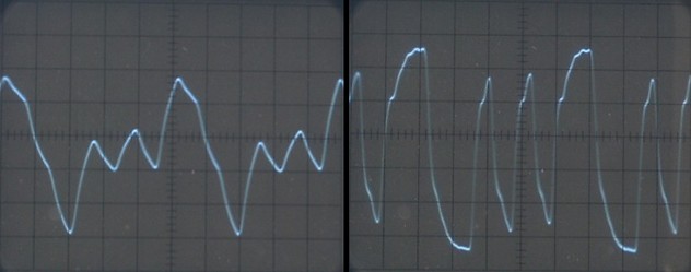
The following screen shots of my (pretty old) oszilloscope show the voltage at the majority gate resistors joint (left) and after the 74AC245 driver (right). The inputs to the M gate are from a 74AC163 counter with the lowest bit running through a 74AC174 register. (therefore bit 0 is inverted, in case you realized this and wondered why). I'm running it through a 74AC174 because the control lines are driven by exactly this ICs on the control unit. The upper two images are running from a 4 MHz clock, thus D0 running at 2 MHz and toggling with 4 MHz, so you can see "how it should look like". The lower image is with a clock of 16 MHz and my oszi has great problems to follow the input, but especially when i look at the output side it looks ok. The 3-resistor majority gate works as expected.
The 2nd test was whether the control line can drive 16 resistors. Therefore i connected the output of the 74AC174 also via a 100Ω resistor to +5V or GND and watched the changes on the screen. The input curves moved very little up or down, and especially the output side shifted only very little. The maximum current drain to the control line in the K1-CPU is 16 * 2/3*5V/2.2kΩ = 24.24mA, and even in this case the control line must be able to pull the resistors' joint voltage far enough across the input threshold of the 74AC245 driver. In my test the output of the 74AC174 - the control line - was loaded with 5V/100Ω = 50mA and it still worked fine, so i hope i'm on the safe side.
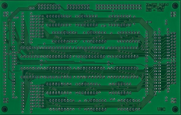
2009-09-16: I have ordered the 2nd PCB of the CPU – the ALU. First i tried to order from PCB-Pool (where i got the first board from) but their web site still becomes unresponsive after a while, so i looked where else to get it done. Now i ordered from LeitOn. Cheaper, but no images from the process, i presume. The order is not yet confirmed.
I have made a short summary of the ALU functions here.
2009-10-09: The ALU PCB arrived. The quality from LeitOn is not as good as from PCB-Pool, but it will work. And if it does not, it's probably more a problem with my design or a chip.
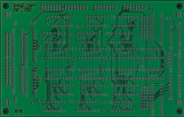
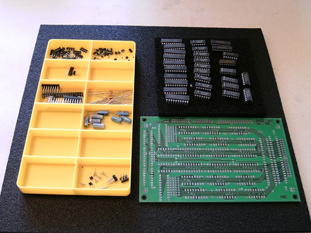
2009-10-10: Starting to assemble. The vias are sometimes drilled (very) slightly excentric and have very little remaining pad, so i measured the resistance of the data paths, which was roughly 1.0Ω in most cases, so i hope they are all ok.
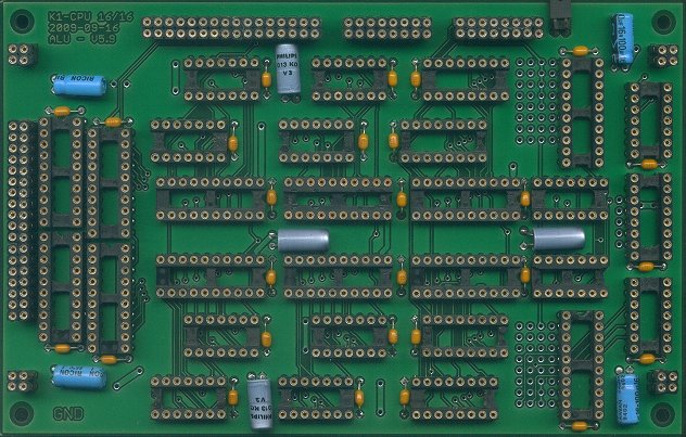
I truncated the resistor networks to 3 resistors for the majority gates. But it seems, this varies the value of the last resistor. Grmbl. I'll have to sort this out the next week. Next image ist after soldering most components, except the resistor networks. I have stacked the bus connectors to give room for the sockets. I decided to use sockets on all boards, because it's easier to exchange a broken IC this way.
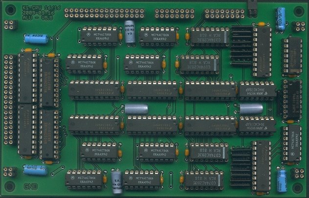
And after populating all sockets:
| Name | Letzte Änderung | Länge | |||
|---|---|---|---|---|---|
| Images/ | 2019-08-20 05:21 | 11 | |||
| majority gate/ | 2019-08-20 05:21 | 10 | |||
| ALU 5.9 circuit connector.pdf | 2009-09-17 20:44 | 21291 | |||
| ALU 5.9 circuit main.pdf | 2009-09-17 20:43 | 79622 | |||
| ALU 5.9 info.txt | 2009-09-16 19:42 | 2763 | |||
| ALU 5.9.brd | 2009-11-03 18:15 | 119574 | |||
| ALU 5.9.sch | 2010-04-09 09:29 | 139205 | |||
| ALU 5.A.b#1 | 2009-11-03 18:15 | 119574 | |||
| ALU 5.A.brd | 2010-04-09 09:35 | 119838 | |||
| ALU 5.A.s#1 | 2010-04-09 09:29 | 139205 | |||
| ALU 5.A.sch | 2010-04-09 09:35 | 139099 | |||
|
majoritygate.gif size: 173 × 100 |
2009-08-16 20:40 | 757 | ||
| part list.txt | 2009-10-10 19:45 | 404 | |||
| wangadder.pdf | 2009-03-08 11:03 | 971737 |
powered by vipsi - your friendly VIP Script Interpreter
![]()
![]()