
|
/Vintage/Sinclair/Other Inventions/Micromatic Transistor Radio/ |
| k1.spdns.de / Vintage / Sinclair / Other Inventions / Micromatic Transistor Radio / |
|
|
/Vintage/Sinclair/Other Inventions/Micromatic Transistor Radio/ |
| k1.spdns.de / Vintage / Sinclair / Other Inventions / Micromatic Transistor Radio / |
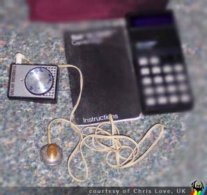 The Micromatic was introduced in 1967 and used the same tiny (45x34x15mm) case as its predecessor. Like the Micro-6, the Micromatic was available in both kit and ready made form. Unlike it's predecessor it used silicon transistors, which with their higher gain, allowed the use of just two devices. The Micromatic retained the regenerative reflex circuit, with the first transistor amplifying both RF and AF. Regeneration was via coupling between the first transistor's collector choke and the ferrite rod, and was adjusted by physically moving the choke relative to the aerial.
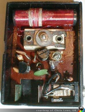 The internal components are laid out as shown in the image to the right, bearing in mind that the picture is inverted – the ferrite rod should be at the bottom. I've presented it this way as most of us are used to seeing aerial at the top and batteries at the bottom. Immediately under the rod is the tuning capacitor, a "postage stamp" mica compression trimmer. Below the trimmer, to the right of the transistor, is the collector choke. At the bottom can be seen the infamous Sinclair battery clips together with the earpiece socket which also served as the on/off switch - inserting the jack plug switches the set on. Two types of earpiece were supplied, crystal or high impedance magnetic. Reception was not fantastic, and that's putting it mildly, but at the time these tiny radios were interesting novelties as well as being amongst the smallest available. [Chris Love]
| Name | Letzte Änderung | Länge | |||
|---|---|---|---|---|---|
|
inside.jpg size: 295 × 388 |
2007-10-17 11:00 | 28784 | ||
|
Micromatic.jpg size: 297 × 280 |
2007-10-17 10:59 | 18001 |
powered by vipsi - your friendly VIP Script Interpreter
![]()
![]()