
|
/Vintage/Sinclair/82/Peripherals/Multiface I, 128, and +3 (Romantic Robot)/MF1/Technical Information/ |
| k1.spdns.de / Vintage / Sinclair / 82 / Peripherals / Multiface I, 128, and +3 (Romantic Robot) / MF1 / Technical Information / |
|
|
/Vintage/Sinclair/82/Peripherals/Multiface I, 128, and +3 (Romantic Robot)/MF1/Technical Information/ |
| k1.spdns.de / Vintage / Sinclair / 82 / Peripherals / Multiface I, 128, and +3 (Romantic Robot) / MF1 / Technical Information / |
Kio 2015-05-10
8 kB ROM paged in at 0x0000
8 kB RAM paged in at 0x2000
NMI button
Kempston compatible joystick port
    There's a wire bridge on the board which, when opened,
    disables bits D6 and D7 when the joystick is read

One 74LS74 with 2 flip flops to store internal state:
    74LS74.1: FF_PAGED_IN      stores whether MF1 memory is paged in
    74LS74.2: FF_NMI_PENDING   stores whether NMI button was pressed

The MF1 has a rear-side port but the /ROMCS entry is not handled.
%----.----.-001.--1-
read joystick and page in or out MF1 memory
--> bits D4..D0 from joystick and D5=0; D6=0 and D7=0 if wire bridge present (default)
A7 is loaded into the FF_PAGED_IN flip flop:
--> A7=0 -> page out    typically used address: 0x1F
    A7=1 -> page in     typically used address: 0x9F
reset FF_NMI_PENDING: terminates NMI signal
the FF's output enables the memory in the MF1 and
disables the internal Rom of the ZX Spectrum by asserting ROMCS.
Reset  by RESET
Set    by the Z80 executing of the NMI vector address if FF_NMI_PENDING
Loaded from A7 when clocked by IN($1F)
the output raises NMI at the ZX Spectrum
and enables the NMI vector address detection
Reset by RESET
Set   by NMI button
Loads 0 (->reset) when clocked by OUT($1F)
resets FF_NMI_PENDING
resets FF_PAGED_IN
if FF_NMI_PENDING is set:
    does nothing
else
    set FF_NMI_PENDING
    -> raise NMI
       and enable the NMI vector detection
Decoded address bits:
%0000.0000.0110.011-
Also decoded: MREQ and M1
A0 and RD are not decoded!
Executing $0066 or $0067 when FF_NMI_PENDING is set
sets FF_PAGED_IN which immediately pages in the MF1 memory.
The whole PCB contains no capacitors. The drawing is wrong.
The NMI button signal which sets FF_NMI_PENDING is gated through a NAND gate which immediately disables the button as soon as this FF is set. This is probably meant so that the NMI can be reset and does not last as long as the button is pressed. But it's completely useless, because it's not required (the NMI is edge-triggered, not level triggered) and it does not work: When this FF is reset by software, this re-enables the NAND gate and the FF is immediately set again by the button, if the button should be still down. The only difference is, that this way a very short 'NMI off' pulse is created, which may immediately trigger another, potentially recursive NMI.
The MF1 has a rear-side through-port but the ROMCS entry is not connected.
Attaching a rom device behind the MF1 will cause bus collissions when the MF1 pages in.
The joystick jumper does not disable the joystick port but only bits D6 and D7. This may cause problems with some games but is probably required for some other hardware, namely some disk drives to cooperate.
In the drawing, there's a diode between the NMI driver and the NMI line on the ZX Spectrum bus. This is wrong. The diode in the drawing is not required, because the NMI driver circuit, as designed, can only pull down. This is perfectly how it should be and the MF1's driver is actually connected directly to the NMI line of of the bus. The diode connects the the rear-side NMI line to the front side. This is to protect the MF1's driver if a rear-side device maliciously pulls the NMI line high, while it's NMI signal is inactive.
In the drawing the ROMCS line is denoted to be an active-low signal. This is wrong, it is active-high, and that's why the driver's input is connected to +5V: it can only drive high.
MF1.rom is the rom image as found on various sites. It is probably a later version.
MF1.gif is it's associated screen shot.
MF1-kio.rom is an image i have read from my own MF1. This is a MF1 with Video-out and no external enable/disable switch. The PCB says MU 2.0 and Copyright 1985. The serial number is 2229, which may be an early model.
MF1-kio.gif shows the menu offered by this rom.
| Name | Letzte Änderung | Länge | |||
|---|---|---|---|---|---|
| circuit.txt | 2015-05-10 19:04 | 3698 | |||
| MF1 (kio 2006-07-13).rom | 2015-05-10 19:09 | 8192 | |||
 |
MF1-kio.gif size: 320 × 240 |
2015-05-10 19:17 | 1065 | ||
 |
MF1.gif size: 320 × 240 |
2015-05-10 19:16 | 1135 | ||
| MF1.rom | 1999-03-31 12:34 | 8192 | |||
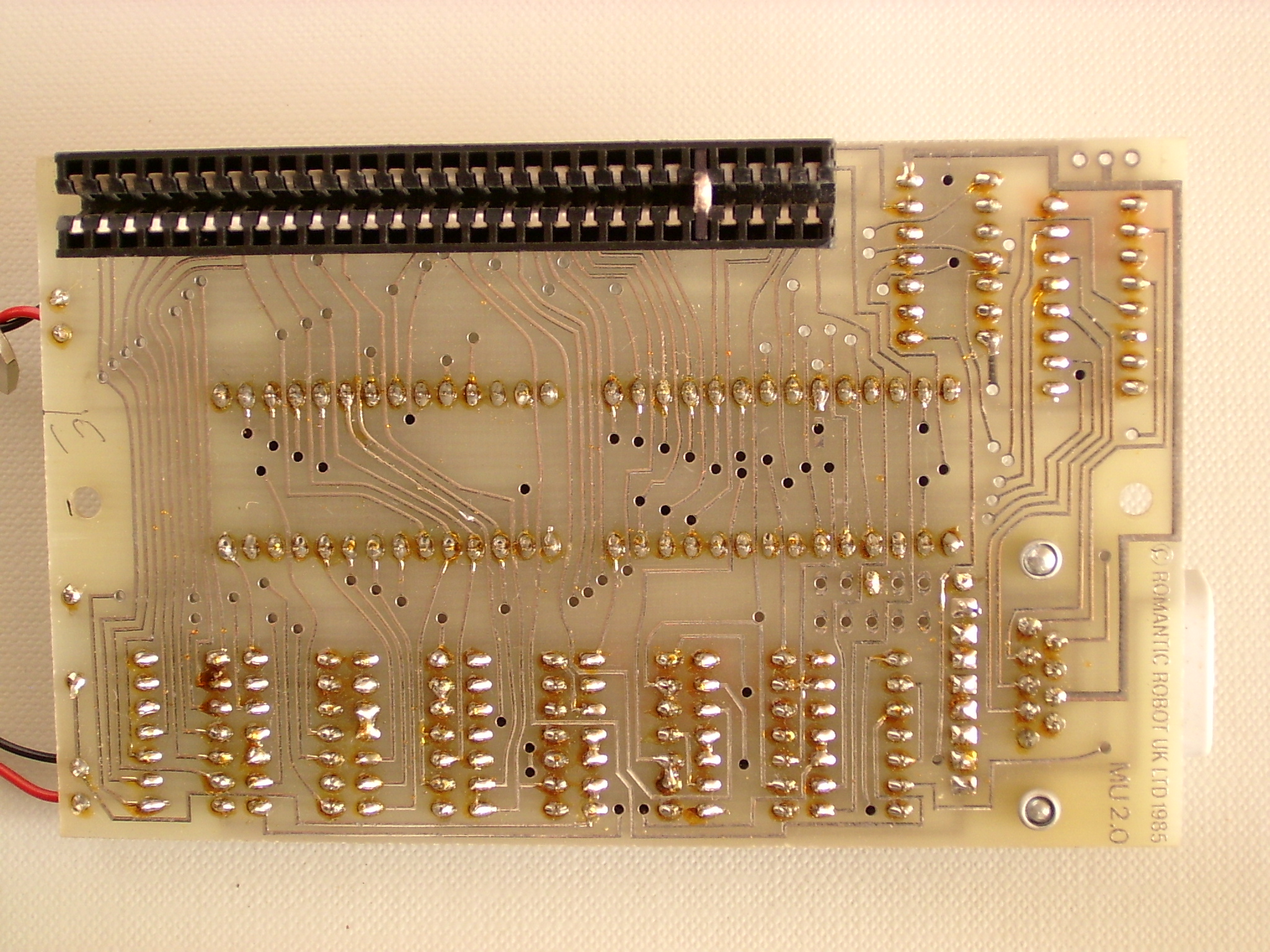 |
PCB rear side-2.jpg size: 2048 × 1536 |
2006-07-13 17:40 | 1297357 | ||
 |
pcb rear side.jpg size: 2560 × 1920 |
2015-05-07 16:19 | 1286223 | ||
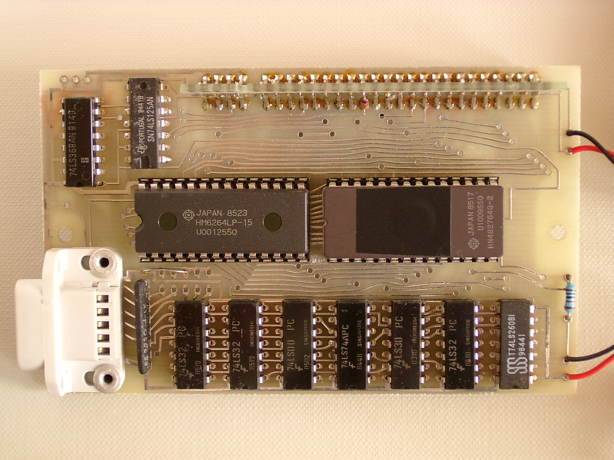 |
PCB top side-2.jpg size: 2048 × 1536 |
2006-07-13 17:38 | 1307526 | ||
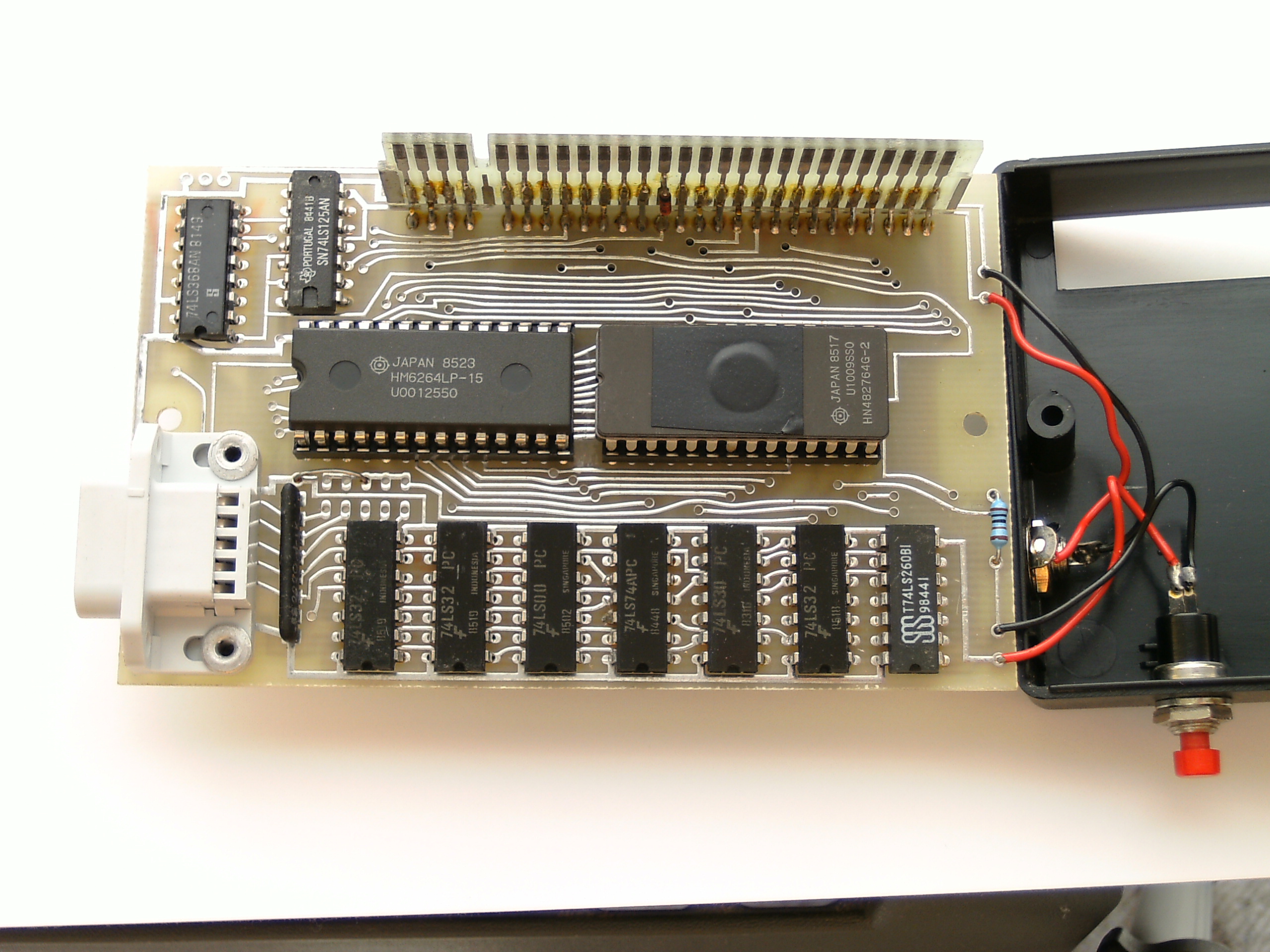 |
pcb top side.jpg size: 2560 × 1920 |
2015-05-07 16:10 | 1105862 | ||
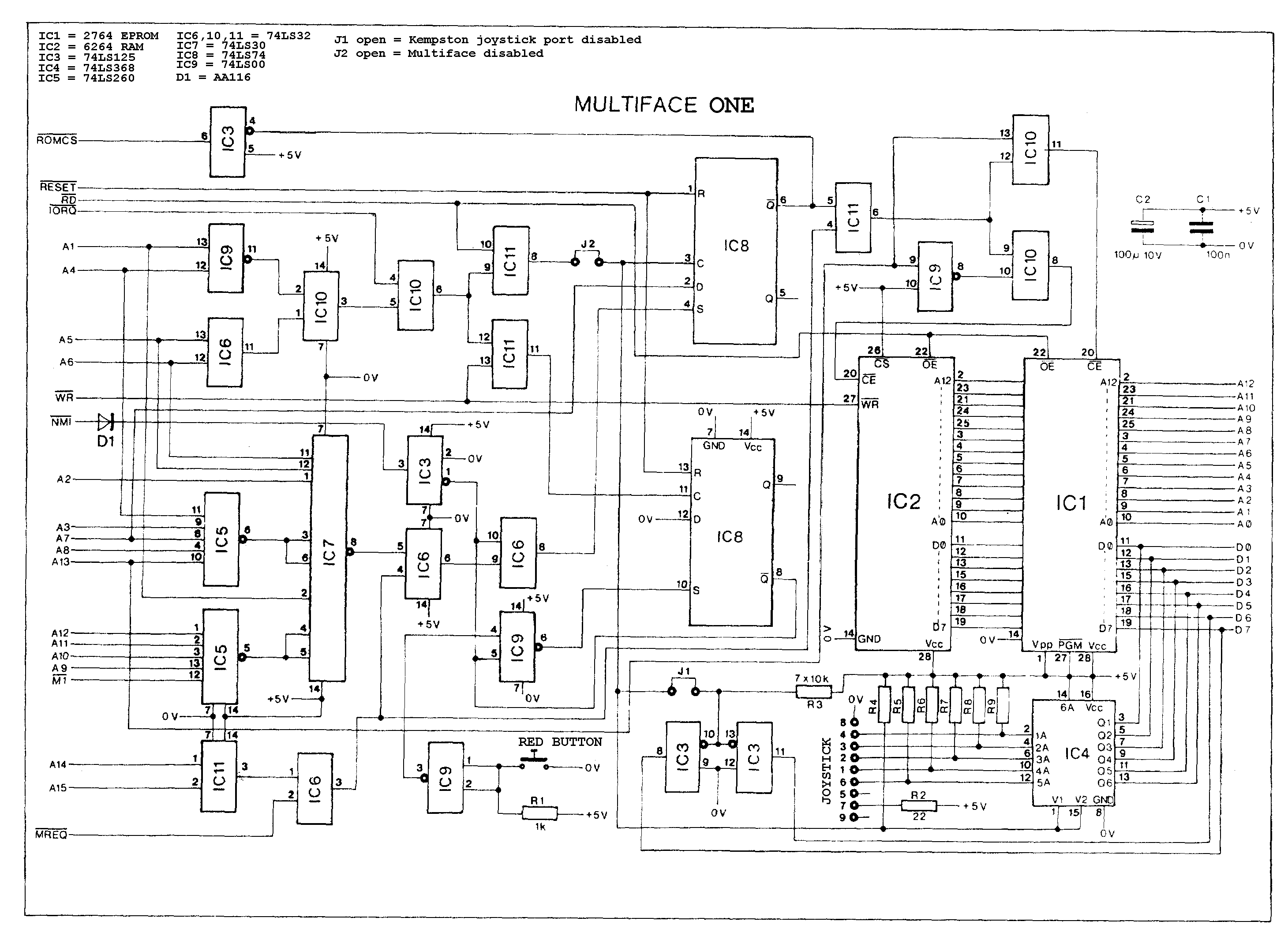 |
Schematics.png size: 2920 × 2131 |
2001-10-12 19:22 | 72709 |
powered by vipsi - your friendly VIP Script Interpreter
![]()
![]()