
|
/Vintage/Sinclair/82/Peripherals/Mouse Interfaces/Kempston Mouse Interface/ |
| k1.spdns.de / Vintage / Sinclair / 82 / Peripherals / Mouse Interfaces / Kempston Mouse Interface / |
|
|
/Vintage/Sinclair/82/Peripherals/Mouse Interfaces/Kempston Mouse Interface/ |
| k1.spdns.de / Vintage / Sinclair / 82 / Peripherals / Mouse Interfaces / Kempston Mouse Interface / |
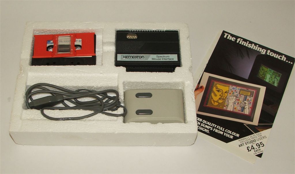
The Kempston mouse interface was compatible with the ZX Spectrum up to ZX Spectrum +2. The mouse had two independent trigger buttons and used an optical system to decode movements of an internal tracker ball. The mouse movements were monitored by the interface itself, and a simple port read returned the X and Y coordinates at any time.
The Kempston mouse interface seems to be technically identical with the Datel GM-7 Bus Mouse, but the pin assignment of the mouse connectors are different!
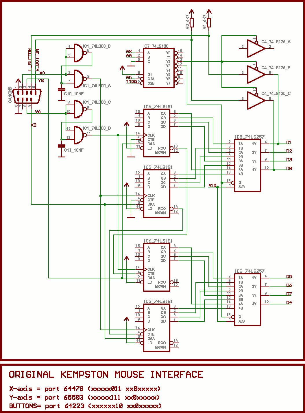
X and Y mouse movements are accumulated using two 74LS191 up and down counters each. A simple port read returns the X and Y coordinates, which can be used to determine moved distance but are not absolute. When the pointer reaches the end of the screen the software must stop there, obviously, and use further mouse movements to recalibrate the offset value.
The interface decodes address lines A5, A8, A9 and A10 for reading. There are no ports to write to. All other address lines may be any value when reading, though as usual the should be set to '1' for not to trigger any other peripherial.
Port 64479 = %----.-011.--0-.----  =  X-axis:  $00 … $FF
Port 65503 = %----.-111.--0-.----  =  Y-axis:  $00 … $FF
Port 64223 = %----.--10.--0-.----  =  Buttons: D0 = right, D1 = left button
The counters are incremented or decremented with each mouse movement and simply wrap across overflow boundary. So the software must at any time assign a certain offset to each counter to map the port read value to the screen coordinate. And this offset must be adjusted when the mouse would move out of the screen, so that the pointer stops there and moving the mouse back immediately results in moving the pointer back towards the inside screen.
When reading the buttons only D0 and D1 are set, the remaining bits left floating, reading in most cases as '1'. They should always be masked out! A button is pressed when the corresponding bit is '0'. ((to be verified.))
The mouse itself is plugged into the interface with a 9-pin sub-D plug, similar to the Atari or Amiga mouse. The pin assignment is as follows:
first row:
    pin 1 = +5V
    pin 2 = X-axis, 1st photo sensor signal
    pin 3 = Y-axis, 2nd photo sensor signal
    pin 4 = left button
    pin 5 = right button
other row:
    pin 6 = GND
    pin 7 = n.c.
    pin 8 = Y-axis, 1st photo sensor signal
    pin 9 = X-axis, 2nd photo sensor signal
The pin assignment is completely different to the Atari or Amiga mouse, even the power lines, so don't plug them into the Kempston mouse interface without an adapter lead!
| Name | Letzte Änderung | Länge | |||
|---|---|---|---|---|---|
| Current Selling Prices/ | 2019-08-20 05:25 | 5 | |||
| Kempston Mouse Interface Driver/ | 2014-10-21 17:13 | 5 | |||
| PCB/ | 2019-08-20 05:25 | 3 | |||
| The OCP Art Studio 48k (OCP)/ | 2019-08-20 05:25 | 12 | |||
| XL/ | 2019-08-20 05:25 | 2 | |||
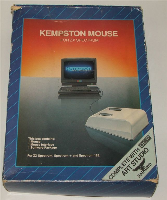 |
Box-2.jpg size: 642 × 768 |
2007-01-19 18:01 | 76568 | ||
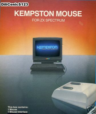 |
Box.jpg size: 337 × 400 |
2005-12-13 17:50 | 19810 | ||
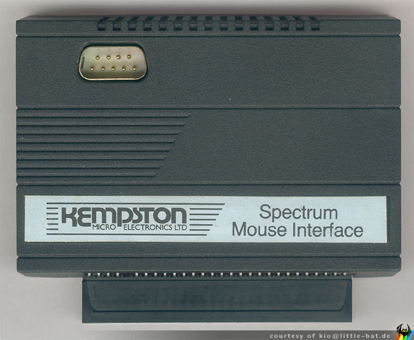 |
Interface - top view.jpg size: 600 × 493 |
2006-07-12 19:17 | 66961 | ||
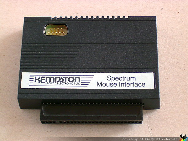 |
Interface.jpg size: 600 × 450 |
2006-07-12 19:24 | 70084 | ||
 |
Kempston Mouse - Schematics.png size: 1055 × 1430 |
2005-12-01 11:11 | 18454 | ||
 |
Styro with items.jpg size: 1024 × 605 |
2007-01-19 18:00 | 83143 |
powered by vipsi - your friendly VIP Script Interpreter
![]()
![]()