
|
/Vintage/Sinclair/82/Peripherals/IF2 Cartridge Interfaces/Sinclair Interface 2/Tech Specs/ |
| k1.spdns.de / Vintage / Sinclair / 82 / Peripherals / IF2 Cartridge Interfaces / Sinclair Interface 2 / Tech Specs / |
|
|
/Vintage/Sinclair/82/Peripherals/IF2 Cartridge Interfaces/Sinclair Interface 2/Tech Specs/ |
| k1.spdns.de / Vintage / Sinclair / 82 / Peripherals / IF2 Cartridge Interfaces / Sinclair Interface 2 / Tech Specs / |
The Interface 2 connects to the rear-side extension port of the ZX Spectrum and provides two Atari-style joystick ports, a ROM cartridge port for instant-on games and a crippled port throughput for connecting a ZX printer only.
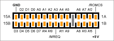
Interface 2 cartridge connector, top view
All lines connect to the named connections at the ZX Spectrum rear port.
/ROMCS is pulled high by the cartridge (it is simply shorted to +5V) thereby disabling the internal ROM of the ZX Spectrum. The ROM cartridge is activated when the CPU accesses memory in the lowest memory page, when A14 and A15 are low in conjuction with /MREQ.
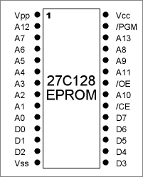 The pinout of the module port closely replicates the pinout of a 128 kbit ROM with JEDEC pin assignment. The 27C128 EPROM is shown to the left. The cartridge slot and the EPROM pinout match exactly, except for the following replacements:
Vpp (programming voltage supply) of an EPROM is not connected to the module's plug. Instead this pin of the Interface 2 slot is connected to /ROMCS of the ZX Spectrum, and it is shorted to +5V on the cartridge to disable the Specci's internal ROM while the cartridge is plugged in.
/OE (output enable) of the ROM is connected to /MREQ of the CPU, so the ROM's outputs are only enabled when the CPU accesses memory.
/CE (chip enable) of the ROM is connected to A14 of the CPU, also as part of the page select logics.
At the position of /PGM (programming enable) is a second chip select /CS or output enable /OE input at the ROM. This is connected to A15 of the CPU, implementing the last part of the page select logics.
The ROM is activated whenever A14 goes low and the ROM's outputs are enabled when A15 goes low and /MREQ is activated. The cartridge cannot distinguish between a read, write or refresh cycle, because the /RD, /WR and /RFSH lines are not connected to the cartridge slot.
The ROM is also activated when a program writes to the ROM's address range or when the CPU performs a refresh cycle with the refresh address in this range. The high byte of the refresh address comes from the CPU's I register.
The interface 1 and other peripherial extensions which incorporate a shadow ROM cannot be used while a ROM cartridge is inserted and in use: there is no way to disable the cartridge ROM temporarily to page in another shadow ROM.
The Interface 2 can only be used to attach a 16 kByte ROM or EPROM to the ZX Spectrum. This was probably the reason why there were only re-releases of 16K games available when the IF2 was launched. This also killed all dreams of simple expansions via this slot. Only a few hackers added timing logics as a last resort to their own cartridges to overcome at least the 16 kB limit. See the Doityourself section.
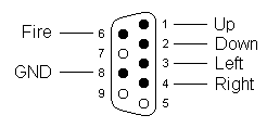 |
| IF2 joystick ports, top view |
The joystick buttons are mapped to the top row of the keyboard. A program cannot distinguish between joystick buttons or direction switches and key presses in the top row. Joystick ONE (the one to the right) appears at keys 6 to 0, joystick TWO (left) appears at keys 1 to 5. It is possible to read the joystick with INKEY$ from Basic, but with the limitation that the standard keyboard routines suppress multiple simultaneously pressed keys. So this method is not advisable. Instead they are read directly with IN.
Sinclair suggests address 61438 (0xEFFE) for joystick 1 and 63486 (0xF7FE) for joystick 2. The switches are assigned as follows:
Joystick   1           2
Address    $EFFE       $F7FE
Bits       %xxxLRDUF   %xxxFUDRL
The bits are shown as a binary number, UDLRF standing for Up, Down, Left, Right and Fire respectively. The x bits are not used and are 1 most time. But don't rely on this, always mask them out!
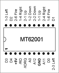 |
| IF2 joystick driver IC, top view |
As can seen from the pin layout of the MT62001 the joystick addresses are decoded with the same minimal effort as the rest of the internal hardware: Only A0 from the lower address byte is decoded, which normally indicates an ULA access (and actually activates the ULA in parallel) and A11 and A12 from the high byte which select the top left and top right keyboard row respectively. Therefore the joysticks will be read with every IN where A0 and A11 or A12 is low.
When A0 and A11 and A12 is low then the MT62001 remains inactive and no joystick is read at all. This is different from the ULA reading the keyboard: Here all keyboard lines where A8 to A15 is low are polled simultaneously. So you may be able to distinguish between a IF2 joystick and a key pressed in the top row.
Try the following program and press keys from the top row and buttons and one or two joysticks:
10 PRINT AT 1,1; IN 59390; " ";
20 GOTO 10
It shows how the input value changes with keys and multiple keys in the top row, but it does not react to the IF2 joysticks, because 59390 = $E7FE where both A11 and A12 are low.
Paul Farrow has drawn the full circuit diagram of the interface 2 at fruitcake.plus.com. The diagram is reproduced here with his kind permission.
 |
| Interface 2 circuit diagram |
Amstrad has changed some signals at the extension bus for these models which affects the printer and ROM port.
The joysticks of the IF2 are not affected and are usable, though these models come with built-in joystick ports, which use the same addresses.
The +9V line is removed from the expansion port, so you can no longer use the ZX Printer. Other printers like the Alphacom 32, which had their own power supply and of course printers connected to the Centronics port still work.
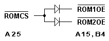 Most annoyingly the cartridge slot does not work, because /ROMCS has been removed and replaced by /ROM1OE and /ROM2OE to control the 64K internal ROM. This can be fixed with 2 diodes, which should be made in the ZX Spectrum, not in the interface 2. The patch is shown in the image to the left. Note that side B is the component (upper) side of the PCB, pin 1 is at the side with the slot.
| Name | Letzte Änderung | Länge | |||
|---|---|---|---|---|---|
| IF2 joystick ports.txt | 2005-12-10 19:17 | 750 | |||
| www.fruitcake.plus.com | 135 |
powered by vipsi - your friendly VIP Script Interpreter
![]()
![]()