
|
/Vintage/Sinclair/82/Doityourself/IF2 cartridges/ |
| k1.spdns.de / Vintage / Sinclair / 82 / Doityourself / IF2 cartridges / |
|
|
/Vintage/Sinclair/82/Doityourself/IF2 cartridges/ |
| k1.spdns.de / Vintage / Sinclair / 82 / Doityourself / IF2 cartridges / |
Since there were only 10 titles ever published for the Interface 2, it seems highly desirable to blow some own EPROMs with adapted games. Two 16K games fit into a 16K EPROM, because there was only approx. 8 kByte of RAM free on a 16K Specci, but most 48K games require larger EPROMs.
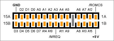
Interface 2 cartridge connector, top view
All lines connect to the named connections at the ZX Spectrum rear port.
The pinout of the module port closely replicates the pinout of a 16 kByte (= 128 kbit) EPROM with JEDEC pin layout. The cartridge slot and the EPROM pinout match exactly, except for the above mentioned changes. Therefore it is very easy and straight forward to connect a 16K EPROM.
But it is very hard even to overcome only the 16K limit and use larger EPROMS, e.g. to instantly load and run 48K games. This requires to add some timing logics to temporarily page in (parts of) the EPROM after power-on.
Also, the module cannot distinguish between a memory read, write or refresh cycle, because the /RD, /WR and /RFSH lines of the CPU are not connected to the cartridge slot. So the EPROM is also activated when a program writes to the ROM address range and when the CPU performs a refresh cycle with the refresh address in this range. The high byte of the refresh address comes from the CPU's I register.
Other peripheral extensions which incorporate a shadow ROM, e.g. the Interface 1, cannot be used while a ROM cartridge is inserted and paged in: there is no easy way to disable the cartridge ROM temporarily to page in another shadow ROM.
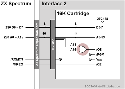 The EPROM replaces the built-in ROM |
This is the standard mode used by all commercial Interface 2 modules. The EPROM remains activated until the Specci is powered down. As said above you cannot use other ROM-based peripherals and it's too small for most 48K games, but you could fit in a small start menu to select from two 16K games.
Or you could build a diagnostics cartridge which starts off using no RAM at all until in a first step it has verified some RAM and e.g. that the RAM paging mechanism of a ZX 128K works as expected.
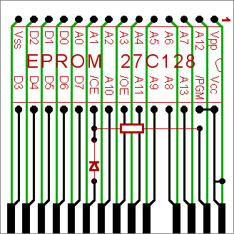
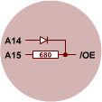 The single OR gate can be constructed with one diode and one resistor. This is shown in the image to the right.
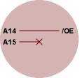 You can even omit the entire gate and ignore A15 and build the cartridge just with the EPROM and no additional components at all.
Then there will be data collission between EPROM data and upper 32K RAM (or CPU) data when you read (or write) to the upper half of the address space. But this can be overcome if the program simply does never read or write to the upper 32K of RAM, that is, if it is a well-behaved 16K program.
 Additionally you should avoid to set the I register to $80 or higher, because the I register is put on A8 to A15 on every memory refresh cycle. Though this should do no harm, because neither the RAMs nor the CPU should put data on the data bus during a refresh cycle, so only the EPROM is activated unneccessarily for a short moment at the end of every instruction fetch cycle.
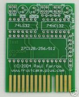
The image to the right shows a superimposed drawing of a 16K cartridge PCB. Black is the top-side layer, green the rear side layer and red are the components. For the version which ignores A15 omit the resistor and the diode and replace the diode with a wire bridge.
Images for a lithography positive, mirrored film for the 16K module are below in the files archive. They are 600dpi b&w, ready for printing on transparency film to make your own double layered IF2 cartridge. They is designed so that you don't need to drill the holes for the EPROM. Just bend the pins up and solder them like SMDs. You need only the 5 holes for the resistor, diode and one connection through the PCB. The EPROM is placed on the front side, with the lower row of pins soldered on the front side and the upper row bended around the top edge of the PCB and soldered on the rear side. I hope you get the idea.
Generally it is hard to use EPROMs larger than the intended 16K ROMs with the Interface 2. This is because the provided signals closely match a 16K ROM's need and nothing superfluous to this task is provided. On one hand the cartridge can not disable more than the built-in 16K ROM, which means, that it can not be accessed at addresses beyond the ROM's 16K range without mixing up with the RAMs. On the other hand you can not use anything but reading memory to signal information such as paging instructions to the cartridge, because only the /MREQ signal is provided and neither /RD nor /RFSH (or even /WR) are present at the cartridge socket. The cartridge can only detect that memory is accessed and it can tell the address. The cartridge can not tell whether this is a read, write or refresh cycle or that a certain address on the address bus is used in an IN or OUT instruction.
So, if you don't want to stick with a bank of DIP switches, where you select a 16K game before you power up your Specci, there are roughly 2 alternatives:
You can either use trigger addresses in the cartridge to flip pages, where you must take certain care that no refresh cycles with these addresses occure. Then the EPROM can be generally remain paged in or, if you constructed it so, be paged out when required to access the built-in ROM or to use other interfaces with shadow ROMs. This would be similar to the way how the Interface 1 pages in it's ROM.
You could eliminate the occurance of refresh in the ROM address range by setting the I register high enough, but AFAIK after power-on and reset all registers are cleared to zero, so immediately after reset memory refresh cycles at the start of the ROM address range will occure.
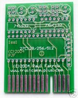
Simpler is to use one or more timers, which start at power-up and flip pages in roughly estimated intervals while the CPU copies their data into RAM. Finally it may be paged out entirely, leaving a loaded system with standard ROM which also can use the IF1. This technique has been used by Paul Farrow at fruitcake.plus.com.
My idea for a simpler 32k EPROM is based on the two data buses in the ZX Spectrum: The contended RAM is connected to the ULA data bus which is loosely coupled to the Z80 data bus via resistors. When the CPU reads from the contended RAM these resistors a low enough to allow proper reading across this boundary. If the CPU reads from other addresses, namely ROM and upper 32k of RAM, then the ULA in parallel accesses the contended RAM. The output drivers of the contended RAM chips and those of the ROM, upper RAM and Z80 are powerful enough to compensate leaking current from the respective other side of the boundary.
Based on this it is not only possible to read from the EPROM in address range $0000–$3FFF (ROM), but you can also read from the EPROM in address range $4000–$7FFF, which is in contended RAM address range. In this case both the EPROM and the contended RAM will put data on their respective buses, but they are separated by the bus boundary and the Z80 will only read the data provided by the EPROM. At this time the Z80 must not write data to the contended RAM (as it must not write to the ROM), because the IF2 module can't distinguish between read and write, as said above, and would also put data on the data bus, which will collide with the Z80 data! The only exception is, that you can read a byte from the EPROM and then write this byte to the same address. Then the data put on the bus by the EPROM and the Z80 will be the same. In this way you can copy EPROM data into the contended RAM. But you will most likely want to copy all data simply into the upper 32K of RAM, because you expect a 48K Specci anyway, because you cannot load more than 16K of data into a 16K Specci.
Booting from such a simplified 32k EPROM would look like following:
I'd like to implement some 48k games this way. I believe that most 48k games should be compressible into 32 kByte. If someone is faster than me then he can happily connect me via email. :-)
| Name | Letzte Änderung | Länge | |||
|---|---|---|---|---|---|
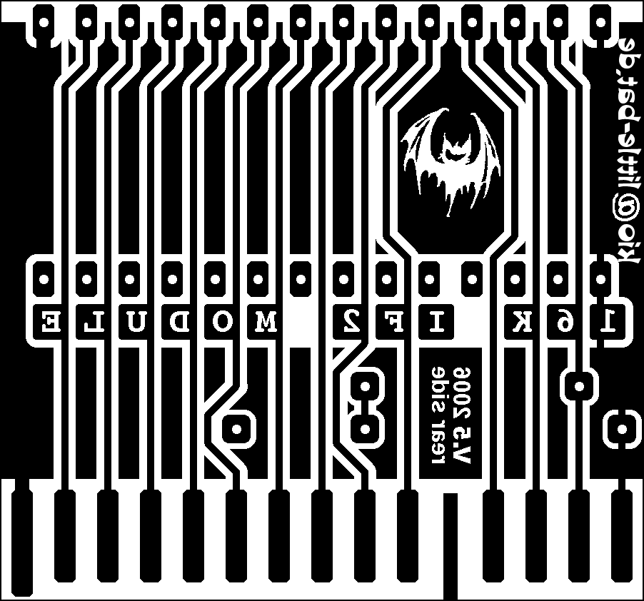 |
16K module v5 rear.png size: 902 × 842 |
2006-08-23 16:36 | 22224 | ||
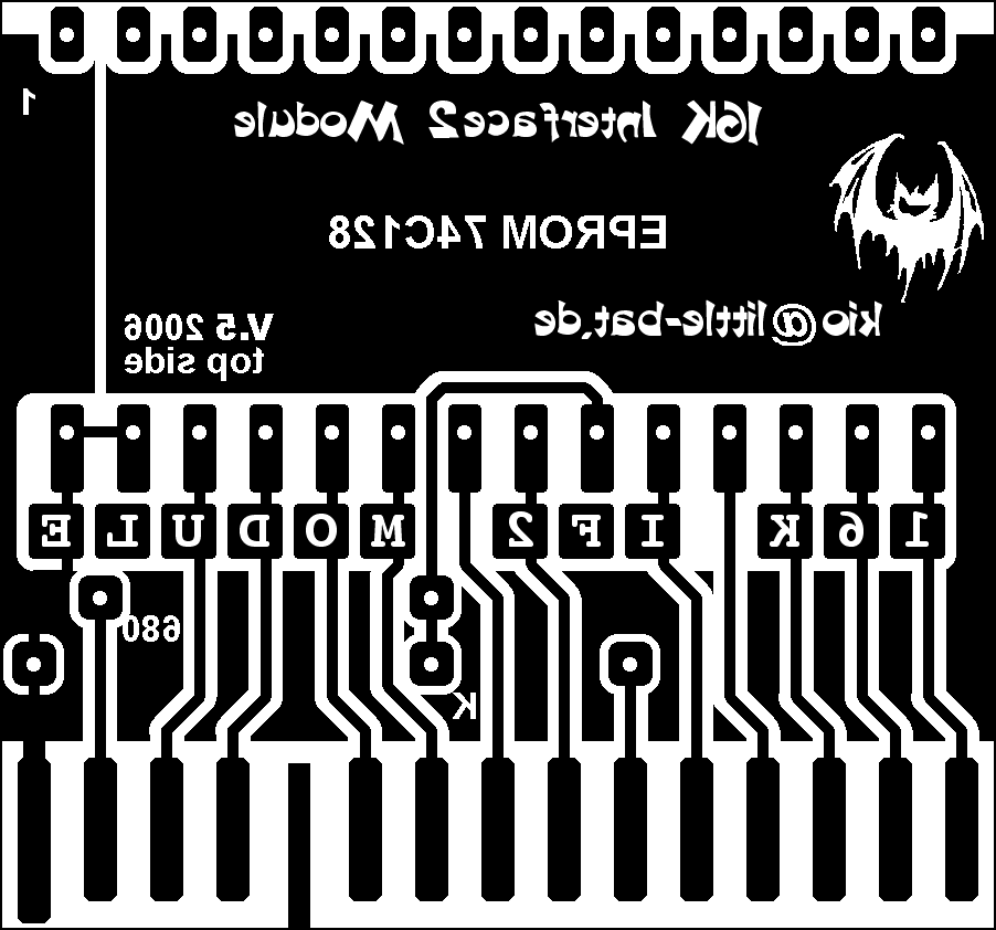 |
16K module v5 top.png size: 902 × 842 |
2006-08-23 16:35 | 27184 | ||
 |
2008-03-18 £5.19.jpg size: 159 × 200 |
2008-03-20 11:32 | 11578 | ||
 |
2008-06-27 £10.50.JPG size: 162 × 200 |
2008-07-04 17:42 | 11077 | ||
 |
2008-07-08 £4.99.JPG size: 162 × 200 |
2008-07-11 18:10 | 11077 | ||
 |
2008-08-11 £6.99.JPG size: 162 × 200 |
2008-08-19 11:57 | 11077 | ||
| CartridgeGenerator.zip | 2007-05-03 10:42 | 29369 | |||
| fruitcake.plus.com (Paul Farrow) | 146 | ||||
| reading IF2 roms [WoS] | 101 |
powered by vipsi - your friendly VIP Script Interpreter
![]()
![]()