
|
k1.spdns.de / Develop / Hardware / K1-Computer / Front Panel / |
 Start
| Front Panel
| Microcode Header
| Frontpanel v1 Start
| Front Panel
| Microcode Header
| Frontpanel v1
|
|
|
k1.spdns.de / Develop / Hardware / K1-Computer / Front Panel / |
| Start
| Front Panel
| Microcode Header
| Frontpanel v1
|
Last updated: 2010-11-06
Questions & comments to Kio
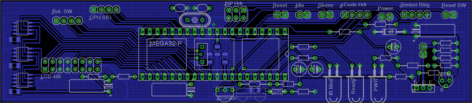
The second version of the front panel is based on an ATmega32 micro controller and provides a 4x40 character LCD, an infrared receiver for a multimedia keyboard with trackball which i happen to own, an IrDA-alike port for remote terminal connection, a data input ring to monitor all CPU bus signals and a data output ring to replace the microcode eprom data at power-up. Of course it will also provide a slow motion clock and microcode single stepper.
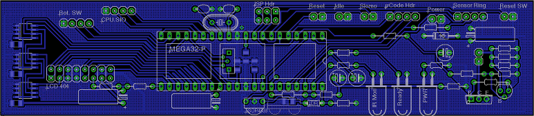
Double-sided Frontpanel PCB
A 4x40 character LCD, maliciously named "404", is connected to port C. Due to shortage of ATmega port pins, only the 4 bit bus variant is connected.
Backlight LED brightness and LCD voltage VO are regulated by PWM outputs, so that i do not need a poti and holes in the frontpanel. A light dependent resistor LDR is intended to regulate backlight brightness depending on the ambient light level.
Three 32kByte serial EEproms are intended to store an alternate microcode for the CPU. They are attached in parallel, so that 3 bit can – and must – be read or written simultaneously. Given a 400 kHz data transfer on the I2C bus, booting the CPU from the frontpanel's EEproms will take approx. 32k*9/4e5 = 0.75 seconds. The data lines are shared with the LCD. I have attached one address line to Vcc, because i don't know, whether i have 24256 (without address inputs) or 24256B (with address inputs). This way i can test it.
For minimal comfort a rotary encoder will allow to browse through the frontpanel menues.
An asynchronous TTL-level serial port is intended for communication with the software running on the CPU. This allows downloading new microcode into the EEproms, usage of the IR keyboard and the 4-lines LCD as a minimal terminal or, with the help of the ATmega, an IrDA-alike connection to a remote host via infrared link. One control line tells the frontpanel whether the serial data should be routed to the IrDA transceiver or is meant for the frontpanel itself.
The serial TxD and RxD lines are planned to be routed over a 3.5mm stereo jack in the frontpanel, one of the few break-throughs accepted. These sockets have switches which connect to a pairing pin if no plug is inserted. This way the serial lines are normally connected internally to a K1-bus I/O board with a SIO chip; but if a plug is inserted, then it connects to the remote host, whatever it may be. I'll have to build an adapter lead which converts the 5V levels to RS232 levels or connects to a USB-RS232 bridge chip later.
Since the ATmega is planned to run at 16 MHz maximum speed, an external clock is required. The internal clock only provides up to 8 MHz. Then the ATmega can no longer be programmed in my simple USBtiny programmer, because this has no clock connected to the target's socket. Programming the microcontroller in place via the ISP link is the better choice anyway. The +5V from the ISP link are not connected to the power supply of the frontpanel board, because this would, in most cases, also supply the whole K1 computer, which would kill the programmers power supply. So i have to power up the CPU. Since the lines for ISProgramming are shared with some functional outputs of the ATmega, i had to take care that this is 'acceptable'. Basically this means that these pins are outputs and that they do not trigger unpredictable results in the CPU.
On the rear side of the case is a reset switch which does not reset the CPU – but the front panel. This will offer to reset the CPU in return.
The 'Idle' output from the CPU is displayed with a LED on the frontpanel and it is low-pass filtered and connected to an A/D input of the ATmega. This way the frontpanel can read in and display a cpu usage graph on the LCDisplay.
The first usage for the front panel was a show room slow motion clock and single stepper. For this the 'clock select' and 'clock' input on the CPU control unit are connected to the frontpanel. They are also needed for microcode upload.
The microcode upload header is connected to the frontpanel. In conjuntion with the front panel's ability to reset the CPU and to generate it's main clock, the front panel can upload a different microcode to the CPU's control unit. The microcode header is a simple 24 bit wide SIPO shift register with 3-state outputs, which are plugged into the control unit instead of or between the microcode eproms and the eprom sockets.
The microcode can be read from the I2C EEproms or directly from the serial port connected to a remote host. Direct upload via IR may be possible too but slower and more challenging.
The sensor ring is a gigantic 96 bit PISO shift register ring located on the CPU's I/O board, which reads in the state of all CPU internal bus lines. This can be used to display the CPU's internal state on the frontpanel, e.g. while single stepping, or to set breakpoints for the CPU.
At the front of the board is an IrDA transceiver. This will probably not be used for a real IrDA link, because IrDA is fat and ugly like TCP/IP and USB and information is only available for members and paying customers. Instead i will eventually design a homebrewn hardware-layer protocol to simply feed a remote serial signal into the frontpanel or to the CPU. And i will probably be able to emit remote control signals via the IR sender led.
The IR led is flashed with 500 mA! Crazy. I had to reroute the power supply on the frontpanel board with respect to this. I had to place the transceiver on top of the board, so that there will be a tidy row of break-throughs in the front plate for all the transceivers and leds.
This is a remote control IR receiver which requires a modulated IR signal, like all remote controls use. It's primary use is to connect an IR keyboard with trackball (mouse) which i happed to own.
2010-03-14: Software development started.
For current state see folder firmware.
| Name | Letzte Änderung | Länge | |||
|---|---|---|---|---|---|
| attic/ | 2019-08-20 05:21 | 15 | |||
| firmware/ | 2019-08-20 05:21 | 34 | |||
| Frontpanel v1/ | 2019-08-20 05:21 | 9 | |||
| FrontPanel.xcodeproj/ | 2019-08-20 05:21 | 5 | |||
| Images/ | 2019-08-20 05:21 | 17 | |||
| OSX-AVR-Tools/ | 2020-08-29 15:16 | 4 | |||
| 24256B EEPROM.pdf | 2008-07-25 10:26 | 179589 | |||
| 404B - LCD 40x4 w:Backlight.pdf | 2009-11-27 14:23 | 29490 | |||
| ATmega16 - AVR 8-bit, 16k Flash.pdf | 2008-02-14 10:01 | 5632448 | |||
| ATmega32 - AVR 8-bit, 32k Flash.pdf | 2010-02-08 14:55 | 2503385 | |||
| ATmega32 - AVR 8-bit, 32k Flash__.pdf | 2010-03-23 20:20 | 5661533 | |||
| avr-libc-index.html | 2015-12-14 17:00 | 642660 | |||
 |
Board 2.4.png size: 1545 × 338 |
2010-02-18 15:36 | 34101 | ||
| board rear.pdf | 2010-02-25 15:34 | 71386 | |||
| board top.pdf | 2010-02-25 15:34 | 143319 | |||
| component placement top.pdf | 2010-02-25 15:29 | 25749 | |||
| CoolTerm.app | 2010-04-15 16:22 | 58028 | |||
| eagle.cam | 2010-02-18 19:13 | 2526 | |||
| eagle.epf | 2010-01-24 14:21 | 1476 | |||
| Faceplate.odg | 2010-03-16 19:45 | 378910 | |||
| Frontpanel 2.4 Circuit.pdf | 2010-02-18 15:31 | 35979 | |||
| Frontpanel 2.4.brd | 2010-03-25 14:41 | 47422 | |||
| Frontpanel 2.4.sch | 2010-02-19 13:17 | 90625 | |||
| Frontpanel 2.5.brd | 2010-03-19 18:57 | 47590 | |||
| Frontpanel 2.5.sch | 2010-03-19 18:57 | 90769 | |||
| TFDU6101E - Fast IrDA Transceiver.pdf | 2009-11-29 16:39 | 688138 | |||
| TSOP48xx RC5 IR Receiver.pdf | 2009-12-27 17:53 | 136838 |
powered by vipsi - your friendly VIP Script Interpreter
![]()
![]()