The Lil Old ZX Spectrum 48k Service Manual

SECTION 4.3 - FAULT DIAGNOSIS AND REPAIR

LIST OF CONTENTS

TV screen dead, smoke appears on switch-on / Not Initialising

TR4 base-collector shorted Remove TR4
Short persists with TR4 removed
  1. Check TR5 and C44
  2. Visually check track
  3. Check TR4
TR4 blows again
  1. Change TR4 and TR5 (even though TR5 checks out)
  2. Check the TR5 circuit components are to latest specification

No video

No video
  1. Change IC1
  2. Check TR1 and TR2
No video after ULA changed
  1. Visually check IC1 and socket
  2. Check for shorting between C65 and R53
  3. Carry out Power Supply Unit check
No +5V input
  1. Check voltage drop across R64
  2. Check +5V regulator O/P and +9V regulator I/P
  3. Check PWR socket not shorted
  4. Check power unit
No VIDEO INPUT at IC14 pin 12
  1. Check waveform at IC14 pin 13. If correct check TR1 and TR2
  2. Check waveforms at IC1 pins 15, 16 and 17
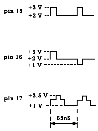
IC1 pins 15, 16 and 17 waveform outputs

If correct check VR1, VR2 (Issue 1 and Issue 2 boards)

3. Change IC1

4. If +5V and VIDEO INPUT correct change modulator
Corrupt Paper, after ULA change

Initial Check
  1. Check IC1 socket
  2. Check PWR socket is not intermittent
  3. Check IC1 pin 14 for +5V with no discernable ripple
No 3MHz at IC2 pin 6
  1. Low amplitude - check R25
  2. Check TR3
  3. Check IC1 pin 32 for 3MHz
  4. Check IC1 pin 39 for 14MHz
  5. Check crystal X1
  6. Check IC1 pin 13 for +3V

Video Incorrect

Dark Screen
  1. Check tuning
  2. Change modulator
Dim `Sinclair` logo
  1. Check +12V
  2. Check C65 for high impedance
  3. Check R52
  4. Check +5V on IC14 pin 3
Wavy lines across screen
  1. Press down on each electrolytic capacitor to see if lines disappear. If so change that capacitor
  2. Check crystal X2
  3. Check/change TR1 and/or TR2
  4. Check/change IC14
Self resetting Check TR6
Random dynamic squares Change C54
Paper area too low Change IC1
Diagonal lines in the border area Change R47
Distorted video
  1. Check for +3V at IC1 pin 13
  2. Change C30

Colour tuning faults (Issue 1 and Issue 2 boards)

Initial check Visually check IC14 circuits
VR1 or VR2 fails to adjust IC14 pin 13 waveform
  1. Monitor IC14 pin 2 trimming VR2
  2. Monitor IC14 pin 4 trimmin VR1
  3. Change IC14
VR1 or VR2 dc shifts IC14 pin 13 waveform Change IC14
Alternate dark lines on screen Change IC14
No colour after trimming TC2:  
IC14 pin 17 not oscillating
  1. Check crystal X2
  2. Change IC14
  3. Change X2
IC14 pin 17 oscillating but fails to tune
  1. Check for broken track
  2. Change TR2
  3. Change IC14
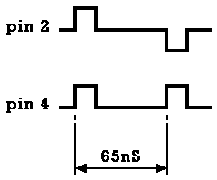
IC14 pin 17 output correct but still no colour (All board Issue numbers) 1. With `Sinclair` logo on screen IC14 pin 2 and IC14 pin 4 should be as follows:

IC14 pin 2 and 4 waveform outputs

2. If IC14 pins 2 and 4 are correct, change modulator

Colour Faults (Issue 1 - Issue 3 boards)

Pin screen Change crystal X2
Blue haze around `Sinclair` logo If untunable (Issue 1 and Issue 2 boards) change IC14
Screen too yellow Change IC14
Intermittent colour
  1. Change TC2 (Issue 1 and Issue 2 boards)
  2. Change IC14
Red, Blue or Green `Sinclair` logo Change IC1
Washed out colours Check TR2

Keyboard Faults

KB1 fault
  1. Check for short on 2 or more of the 5 tracks
  2. Change membrane
KB2 fault
  1. Check for short on 2 or more of the 8 tracks
  2. Change membrane
Dead keyboard Change IC1
Wrong keyboard response Change IC1
Keyboard response too fast Change IC1

Regulator Coil

Coil excessively noise Change coil

Speaker

No speaker output
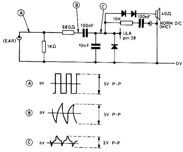
  1. Check load input waveforms
  2. Check TR7
  3. Check D9
  4. Change speaker

Speaker Load Input Waveforms

Speaker Load Input Waveforms


back to Section 4.2
return to Service Manual Index
continue to Section 4.4