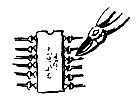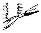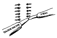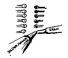


Please read this and study the diagrams fig 1-0 on soldering techniques used on the repair of Home Micros. It is no use tracing the fault/s and then through carelessness causing other problems.
Do not use solder wick to desolder, use a good Solder Sucker, that has a good sucking action and a undamaged tip. The soldering iron should be of 12-17 watt small bit type. It should always have a clean flat tip, it can be kept in this condition with the occasional use of a small file.
To desolder always have the flat uppermost, make sure the end and edge of the tip is tinned (to tin, apply a small amount of solder to a clean tip, then wipe the excess on a small piece of damp sponge). Using the tip of the iron this way round will allow you to get the nozzle of the sucker right over the leg of the chip.
The approach you will find out most successful for removing known faulty IC's, is first to cut the chip off the board, cut at the knee of the leg. Next remove with tweezers the cut legs, while holding the iron on the leg. Now turn the board over to the main track side to desolder the holes. Place the iron on the track, just to the edge of the hole and wait till just molten, place the sucker nozzle over the hole and fire the sucker, at the same time removing the iron. If you find that a hole is difficult to clear, then apply a small amount of solder on to the hole and try again, this gives the sucker something to suck on. That is allowing the sucker nozzle and collection tube are clear. To improve the sucking action of the sucker, apply some WD40 down the nozzle
To remove and IC that you are unsure of and use again if it is found not to be faulty, then use the following technique. Turn the board over onto the main print side, apply the iron as mentioned previously, placed on the outer edge of the leg. Wait until you see the solder flow, then again as above, bring the nozzle right over the leg and fire the sucker, at the same time withdraw the iron. Also to get a gap showing on either side of the leg, on a centrally positioned leg. On IC's who's legs are at the edge of the hole then obviously aim to achieve a gap at the outer edge of the leg.
The leg will still be held on it's edges, these can be broken away by using the extreme end of the iron tip and use a flicking action on the tip of each leg. Do not hold the iron on two long, which would cause the joint to be remade, just long enough as to flick the leg and break the bond.
 |
|
Cut on knee of leg |
|
 |
 |
Cut all legs using small snips |
Use tweezers and iron together |
 |
 |
| Iron on outside of the IC and use a good solder sucker with a small tipped Iron together | Clean any splashes or slivers of solder using a small bladed modelling knife |
 |
 |
| Iron always on the outside of the IC when the solder is molten fire the sucker, at the same time withdraw the iron. Try to achieve a good gap around each leg. If the joint will not clear, then apply extra solder. This will give the sucker something to suck on. | Use the very end of the iron tip and use to flick the leg tip to break any hold the hole might still have. Do not hold the iron on too long or you will re-solder. Carry out both ways on the legs. |
 |
|
| Using a small screwdriver carefully push each leg towards the IC. You should feel and hear the leg come free. If any resistance is felt then re-solder the leg again. Turn the board over and check to see if each leg is free. When you are sure and only then, lift the IC from the board | |
Now turn the board over to the component side, with a small screw driver gently push each leg towards the chip body. If any resistance is felt, then desolder the offending leg again. You should here of feel the leg come free, now turn the board back over to the main track side and flick each leg with a small screwdriver to check they are free in there holes, use half a wooden peg or similar device, not anything metal which would damage the track under the IC. Position carefully under the IC, the IC should now come clear of the board. If it feels as though it is tight, then check each leg again, this is most important, or you could find the print track lifting with the IC.
On some IC's one leg may still remained soldered, this is caused by the amount of copper track area attached to the leg, this absorbs most of the heat from the iron tip, stopping the solder from melting all the way down the hole. If this is the case, then desolder as mentioned and lever the IC from the opposite end, when you get to the still soldered leg, apply the iron from the track side and gently pull the IC clear.
You must now check that there are no solder splashes, old legs or slivers of solder bridging any tracks. Check also to see that the solder pads which incorporate the hole for the legs, has not detached from the track that feeds it. Using your test meter on 20k resistance range, with one probe on the solder pad, measure to a point further along the track to check the connection. This is a prime fault when removing IC's from the board, especially on the Spectrum range, BBC and Electron. To repair any damage due to the above, then pre-tin a small piece of fine wire, scrape any solder resist off the track adjacent to the pad. Now push the wire through the hole, bend a small amount over to rest on the cleaned section of track and solder it down. Take care not to bridge across any adjacent tracks and also do not get solder into the hole in the pad, this would stop you fitting a base.
Always use bases/sockets after taking out any chips, it is much cheaper and easier to cut out a base, then to desolder a replaced IC if you have caused any problems. If you have had to repair any broken tracks with wire, then when you fit the base, wrap the wire end around the base leg a couple of times before soldering. Also try not to keep the iron on longer than is necessary, or you will find the connection to the track above desolders and this is now under the base you have just fitted.
It is very important that you check your work after every stage, it may seem tedious, but can save you hours of extra work, just for that extra couple of minutes work. So please take your time, do not rush and above all, check, check and triple check.
return to the Table of Contents