
There have been literally millions of these computers made and sold, they still represent the highest demand for repair.
There are mainly two types of Spectrum, the first type was Issue Two and the second, Issue 3 - Issue 6B. The differences are only small, but all repairs on these units are covered together, for all practical purposes, all the faults are basically the same.
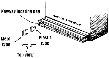
First, the reason for at least 80-90% of faults on these computers. The primary cause, is plugging or unplugging any interface onto the computer while it is switched on. Interfaces, are any add on unit that plugs into the expansion slot, found at the rear of the machine. The largest of which is the joystick interface. In a lot of cases, the customer does switch off before plugging or unplugging the interface. The reason a fault then occurs, it that the Keyway Locating Peg that is fitted on the interface plug, drops out, this allows lateral movement of the interface. This in turn allows the Spectrum O/P's to be shorted together. Considering that most of the IC's are hung on this O/P port, a multitude of faults can occur. Some of which can be uneconomical to repair. fig 4 - 8.
Figure 4-8 |
Important - Never Plug or UnplugANY Interfaces While the Computer is SwitchedON |
 |
The plastic peg can drop out with constantuse. If missing then make a replacement as shown below and Super Glue into position |
The curve over on the metal type, to produce width to the peg can flatten down. This causes side to side movement and therefore can cause problems |
 |
Carefully cut the hinge section of an old cassette box, then cut a replacement shaped peg from this |
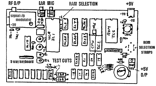
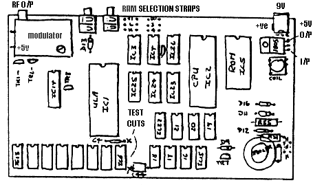
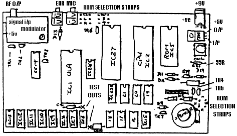
There is however, a sequence of tests that can be carried out, without the aid of complex equipment. Appreciably cutting down the time required to diagnose the faults and without use of oscilloscopes or logic probes, using a Digital multimeter on the DC 20v range and 20k resistance range. All readings will be related to these ranges. In most cases, the Negative lead of the meter is attached to the modulator case. Before you try any IC's change the ULA IC1 6C001 / 5C112 for your first test, it is based and can cause many faults. For a computer that will not initialise, Lines, Squares, Flashing colours and/or Black and White bars, in fact any faulty display, other than the correct one, then read on. fig 1-8. Quickly power up the computer and measure the 7805 regulator, right hand leg with tab away from you. o/p 4.85 - 5.2v is usual. If anything above this, change the regulator and hope not too many chips are down. If it is lower, but not lower than 4.3v, then you have a short somewhere, feel the chips to see if any are hot. The ULA IC1 6C001 or 5C112 (interchangeable) does run quite warm, all others run cold. If the 5v is all but missing, then replace the regulator, but do not run the machine yet.
Switch the Multimeter to the 20k resistance range. Measure the resistance between pin 1 (top left leg) of IC6, the reading should be above 12k on this test, if lower, nick the track to the right of C4 (situated above IC6). Now measure pin 1 of IC6 again, if still low, measure pin 8 of IC6, if below 700 ohms nick the track to the left of C44 100mf 16v (situated bottom right corner IC6).
Leave the tracks cut and power up the computer. Measure on 20v DC range, the right hand side of the first cut (above IC6) , this should read -4.5 to -5.2, if within this range, then measure to the right of the second cut. This should read +11.5 to +12.3, if this is also OK go to the next but one paragraph.
Figure 1-8 |
 |
 |
 |
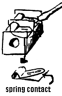 |
Carefully push downwards and inwards, until the spring contact touches the case |
If you are now reading this, then one of both of the last voltage checks, were lower than they should have been. Replace TR4 ZTX650 (if another type of transistor is fitted see fig .) also replace TR5 ZTX213 (do not be tempted to fit any other kinds of transistors here, THEY WILL NOT WORK. You may also visually check , to see that R79 2k2 (Issue 6) or R62 15R (Issue 6) or R55 56R (Issue 4 and less) are not discoloured. If any of the 55R resistors are badly discoloured, change D15 BA137 on all models.
Issue 6-6A
Issue 3's & 2
There is also a 20% likelihood, that the COIL (transformer) has gone shortened turns. You could change it now, or risk taking out TR4 again (no big worry, but you will know the reason if it cooks). Power up the computer, you should hear the coil buzzing. Anyway, check for the -5v and +12v as you did in the last but one paragraph. You must now have the required voltages to run the lower RAM. If not double check, transistors, diodes etc. and any components you have replaced.
Those of you, who arrived here early, you have now joined the ones mopping there brows. You still have the cut tracks, but should now have the +5v out of the regulator, -5v and +12v to the right of the cuts. We now check to see how many 4116's are down, IC6 - IC13 200ns. if any, Switch to the 20k resistance range and again measure pin 1 of IC6, if lower than 14k, but higher than 11k, there is a good chance that at least one RAM chip is down. Now check pin 8 of IC6 if the meter does not read, if all well and good, it should be above 20k. If the measurements are approximately within the above Pin 1 above 11k and pin 8 above 20k, then goto the next but one paragraph.
If you are reading this, then leg 1 was below 11k and/or leg 8 was below 20k. If leg 8 was below 20k, cut each leg 8 of all the lower RAM IC6 - IC13 leaving enough stub on the chip/s, to resolder the leg back, if required. Now still on the 20k range, measure each chip stub, any that are below 20k, cut the chip of the board. Now again measure leg 1, of IC6, if the reading is still below 11k, then cut each leg 1, of the same chips. Any chip stubs that measures below 12k, then cut the chip out. Now you can carefully spot solder all the cut legs, back to the chips that are left. Take all the legs out of the board and desolder the holes, as described in 'Soldering Techniques'.
Those of you who jumped the last paragraph, think yourself lucky. We should all be here now, you can carefully solder across the nicks you cut, taking care you don't bridge any tracks. Now we will power up the computer for a quick test. You should now have -5v on pin 1 of all the IC's that are present, between IC6 - IC13 and also the +12v, on leg 8 of all the said chips. Now feel each of the above RAM chips in turn, none should be even warm, allowing any previous soldering heat to diminish first. Any that are warm, then cut out. Switch off first . . .
If you are lucky and you had no chips with leaks, or getting warm, then you could well have a working Spectrum, if that is the case, there are some further texts that are yet required, but you may jump the next few paragraphs.
For those not so fortunate, then switch the meter to 20k range and measure leg 2, or hole 2 if the chip is missing. You should expect a reading of around 500R, but this is not really important. The important thing, is that they are all practically the same. Any that are found to be exceptionally low, take note of the reading. Then add 9 to the number of the IC that you are checking (ie IC9 faulty + 9 = 18 = IC18) then check leg 2 of that IC, it will be one of the upper memory RAM's, IC15 - IC22 4164, 4532 L3 or L4, 3732 H or L.
Now, if the second reading is higher, (IC15 - IC22), then goto the next paragraph. For those still with us, you should now have a reading, lower on leg 2 on a chip or chips (IC15 - IC22), if not you are lost !. The chip/s require to be tested to see if they are at fault or not. To do this, we carefully cut leg 2 and 14, measure the chip stubs 2 and 14, if they measure anything less than 20k, then the chip is faulty.
Before cutting the chip out, measure the cut legs 2 and 14, if they still measure low, then you will not have to check the CPU, IC2 Z80A and possibly the ROM IC5. If these IC's are based, then life each out in turn, then re-measure leg 1 or 14, obviously if the resistance rises when the IC is unplugged, then replace this chip. If they are not based, then still on the 20k range, measure legs 7,8,9,10,12,13 and 14 in turn, any that measure low, cut them the same as previously. Measure the chip stub, if low the CPU is faulty, now measure the leg, if low then the ROM must also be at fault. Now spot solder all the legs back on the chips that tested OK. Cut out all the chips that are low, take the legs out and desolder the holes as described in the 'Soldering Techniques' section, then base before replacement.
We are now at a point, where you may have changed numerous chips. Before you fit any replacement chips in there bases. Do a quick resistance check on IC6. The following readings should now apply, Pin 1 more than 12k, Pin 8 more than 700R, Pin 2 or 14 the same as all Pin 2's on IC6 to IC13.
Now you can put the new chips in there bases, watch for putting them the wrong way round and for legs straddling the base or bending under.
You could well have a working Spectrum by now, if not, don't despair quite yet. On the other hand if it does work, then there are still some further tests, to carry out before returning it.
Now one thing is for certain, if it still is not working, the display, will be a lot different in design, then when you started. This can help us find any other chips that may be faulty.
Alternate thick black & white vertical bars, with or without flashing pieces. Check CPU IC2 is plugged in correctly, or any legs that were cut are resoldered, also check the ROM, IC5. Test or change TR6 and TR3 both ZTX313's, if OK re-measure legs 2-14 of IC6 - IC13. If OK, let the computer cool down for five minutes, then measure accurately legs 1 of IC6 (should be above 13k), now run the computer for five minutes. Again measure Pin 1 of IC6, if it has dropped significantly, then suspect any of the remaining 4116's that have not been changed. If there are only a couple of the originals left, then it would be prudent to change them. To help find the culprits, leave the computer on again for five minutes, then feel if any are getting warm, if so, you are lucky. If not, cut pin 1 of each chip, just after switching off and measure on 20k, any that are below 13k replace.
Screen full of bright, shimmering, fine herring-bone pattern. Check for -5v on leg 1 IC6, it may have vanished, if so change TR4. Check that all the cut legs are joined correctly, especially leg 1 of IC6 - IC13.
Black screen, with lots, or just one or two vertical very thin dash lines. This is more than certain, to be one or more 4116's (so you have missed one). Also check the ULA, IC1, for straddling legs, bent or damaged legs.
A blank, black screen only, no lines or anything. The likely cause, is one of the upper RAM, IC15 - IC22, cut pin 2 - 14 of each chip, that have not previously been replaced, trying the computer between each chip.
Flashing blocks, or a mixture of above, make sure, both legs of each upper memory chip that may have been cut, have been resoldered correctly. Check ROM is correct type for links and also plugged in correctly. If the original ROM, then check any legs that may have been cut. If at fault then replace ROM.
If you are reading this then the +5 volt regulator O/P, -5 and +12v are present on IC6, also no shorts or leaks measured on IC6 - IC13. If this is not the case, then read the earlier fault finding details.
Computer will not load games or run games properly, but goes through all the correct sequences, ie Loading bars show OK, find Program name, perhaps shows Screen picture, then locks up or resets. Then this is most certainly a RAM fault. To see how much RAM the computer can find and in theory use. Now enter this line of program (no line numbers required).
PRINT PEEK 23732 + PEEK 23733 * 256 (Enter)
If the computer is a 16k (upper 32k not fitted, only a very few of these are around), the answer printed on screen should be 32767. If the computer has 48k, then the answer should be 65535, if all is well with RAM.
If the result is lower than what is expected, then we can trace which RAM is causing the problem. The computer has already given a clue, by telling us how much RAM it can see.
To find the RAM/s that are at fault we now enter a couple of program lines, no line number required. For clarity of explanation, we will use an example.
First as mentioned earlier, we enter :-
PRINT PEEK 23732 + PEEK 23733 * 256 (Enter), the screen now shows 55467 (this number for example only, this could be any number).
Now we enter :-
POKE 55468,85 : PRINT PEEK 55468
We have added 1 to the above number, this being the next memory location the computer cannot see, we then try to push 85 into that location. The colon is important, the next part of the program line tells the computer to have a Peek at this memory location and print what it finds on screen.
If the answer is 85, then enter :- (if anything other than 85 then see Faulty RAM Location Chart).
POKE 55468,170 : PRINT PEEK 55468
We have repeated the last program but substituted 85 for 170, if the answer is anything other than 170 see the Faulty RAM Location Chart
EXAMPLE:
PRINT PEEK 23732 + PEEK 23733 * 256 (Enter)
54876 (Example number is the amount of RAM available, shown on screen)
Add 1 to this number = 54877 (This is the RAM location to test)
POKE 54877,85 : PRINT PEEK 54877
85 (This is the number returned to screen, which is correct, we now have to try the next test)
POKE 54877,170 : PRINT PEEK 54877 (We now push 170 into this memory location).
168 (Because this number is not 170, we look at the above Chart at the 170 column. Look down this column for 168, then across to the column (More than 32767). It will be seen that IC16 would be at fault).
You may now of course have more than one RAM at fault, you will therefore have to run through the above test again, until the computer can see all the RAM.
If you find the above test, does not give the required results ie you Peek back to screen a number that is not shown. There is every likely chance, if either IC's, IC15 - IC22 are based. The leg/s may be bent or straddling the base, or that IC26 74LS157, IC25 74LS157, IC23 74LS32 or IC24 74LS00 are at fault.
Character break-up when the computer is warm, is nearly always caused by IC1 5C112/6C001 (ULA) at fault.
Intermittent crash out or resetting, especially when the computer is moved, can usually be caused by the Power plug or the Power socket, do not attempt to tighten the socket, replace with a new one.
Black dashes or dots appearing when computer gets warm, computer then locks up. This is a typical fault of the lower RAM IC6 - IC13 4116 or could also be caused by the ULA IC1 6C001. You will have to do Resistance check on Leg 1, when the computer is still warm. This is fully covered in the previous sections.
No colour, on ISSUE 2 adjust TC2, VR1 and VR2, if still at fault, change IC14 LM1889. On other ISSUES change LM1889, but I might add, this is a very reliable IC. On some later ISSUES, an SN series of IC was used in IC14 position and was always the cause of no colour. This should be replaced back to an LM1889, even though they have a different leg count, the board still has provision to take the LM1889.
If the Spectrum shows the loading bars, but does not show the program name, it is highly likely that the tape recorder or the tape is at fault. Clean the tape head with Methylated Spirits and adjust the tape head azimuth.
If the program name is replaced with '????????????', then it will be found that the volume setting is too great, reduce the volume on the Tape recorder and try again.
If intermittent loading occurs, then check the MIC sockets contacts for tension, you can re-tension these, rather than replacing the socket, see fig 1-8.
If it is found that no loading bars are present and the Tape recorder is known to be OK. Then first change IC1 5C112/6C001 ULA, if this does not cure the problem, then check the MIC socket as mentioned previously. If all else fails then the culprit is most certainly to be D9 IN4148, found behind the MIC socket.
Loads OK but no sound, the cause can be one or a combination of a few components. First the quickest to check is IC1 5C112/6C001 ULA, if IC1 is OK, then enter this program line :-
10 BEEP 1,1 : GOTO 10 (Enter) RUN (Enter)
Leave the computer on, disconnect the Keyboard after entering the above program. Carefully hold a replacement speaker across the existing one, if you hear a tone, then replace the speaker. On ISSUE 2 computers one of the above will now have you working. On ISSUE 3 and above, change TR7 ZTX450 (ZTX650/1 will be OK), also D9 IN4148, these are found to the left of the speaker.
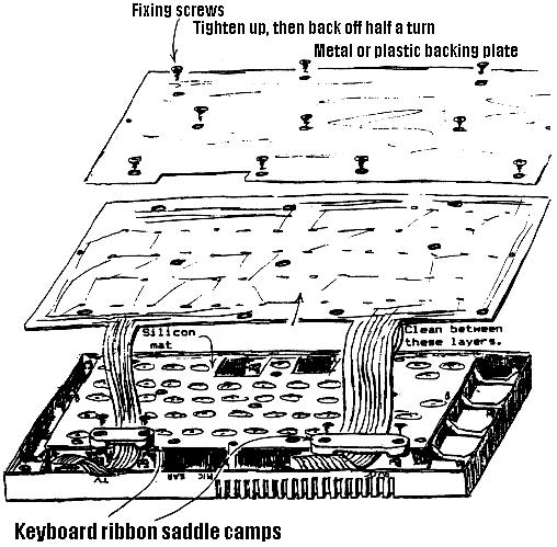
Most keyboard faults on the Spectrum range, are caused by failure of the keyboard membrane. The pads under the key/s wear out or the ribbon section of the membrane cracks with age or misuse. It is very important when carrying out repairs on the computer, that when connecting or disconnecting the ribbon cables from the board, that great care is taken, especially when plugging them into there sockets. The technique, is to apply a slight side to side movement, at the same time, gently easing the ribbon downwards into the connector. See fig 2-8 for Spectrum and fig 3-8 for the Spectrum Plus Keyboards.
If it is found that key/s go faulty when warm and the IC1 5C112/6C001 ULA is OK, replace the membrane.
On Spectrum Pluses the fault of some keys not working, especially the key/s on the bottom row. A cure without having to replace the Membrane can sometimes be achieved. You will see that both ribbon cables are clamped down to the keyboard case, remove the clamps, now carefully clean, with WD40 and a cotton Baby Bud between the different layers of each ribbon, immediately around the area where they are clamped. When re-clamping the ribbons, place some extra packing between the ribbon and the clamp.
On the Spectrum Plus range of computers, the cause of a character being printed on the repeatedly, is caused by the Keyboard Membrane Backing Plate clamped too tight. To cure the fault, remove the keyboard top, you will then see a plastic or metal plate, held in place by nine screws. Slacken by quarter of a turn the screw/s that are nearest the offending key.
If you find that the ends of the ribbon cable are crinkled, creased or cracked, then you can successfully reduce the ends by up to one inch, to get back a good section of ribbon. Do though, reduce the insulated part an extra 1/4 inch or so, or you will find the keyboard will stop working altogether, this is applicable to both Keyboard types.
Figure 2-8 |
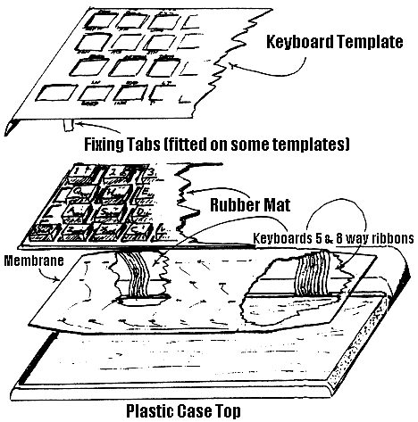 |
Figure 3-8 |
 |
The Spectrum PSU suffers mainly from the wire/s in the pre-moulded plug or lead exit from the box snapping or going intermittent.
The power plug fault is easily cured, by fitting a replacement 2.1mm Female plug. Ensure that Negative goes to the centre, which should be the traced wire. When the plug has been fitted, fill the plastic cover with Silicon Rubber before screwing up. This has the effect, of not only stopping future internal shorts in the plug, but also helps take the strain off the solder connections when the wire is pulled.
At the other end of the lead, if the moulded exit is found to be at fault. Then split the PSU box, making sure that it is disconnected from the mains and computer first. Cut off the faulty section, tie a double knot some three inch down the cable. Now slide the one inch of protective sleeving onto the lead, re-solder the wires from were the old ones came, taking note where the traced wire came from. Now replace the top, with the knot on the inside of the box and trap the sleeving at the exit point. The knot obviously stops the internal solder connections from being strained when the lead is pulled and the sleeving protects the wire at the exit point.
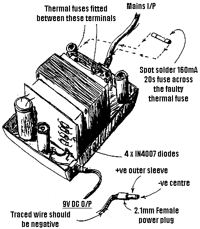
In some cases, the wire will be bare, at the plug or box, this obviously shorts out the PSU, with the effect of blowing the Thermal fuse or/and taking out all the rectifiers, IN4007's, these faults can be repaired. In some cases the transformer can also be faulty, this is only the fit for the bin. To repair the PSU see fig 5-8.
The Thermal fusible link can be replaced, by spot soldering a 160mA Slow Blow 20mm fuse across the old device.
Figure 5-8 |
 |
There are quite a number of different PSU manufactured for the Spectrum, but the general layout is similar. The thermal fuse fitted to some units is found on the circuit board, also some units only two diodes (full-wave rather than a bridge rectifier system). They do have the same faults common to them all, so repairing the units as above should give you a working unit, when done.
The Spectrum range of computers use half working 64k RAM chips for there upper 32k of memory. That being said, only 32k chips are required. A normally working 64k chip is made up of an upper and lower section each of which is 32k. When checked after manufacture that if half of the 64k chip is a faulty, it could be the upper section or the lower section, it can then be restamped as a 32k high section or the lower section RAM. The reason I mention this is because it makes it easier to understand why you have the selection straps. New or replacement RAM for the Spectrum basically comes in three types, of which you can mix two of the types.
Any 4164 200ns will work (even though you are only using 32k or any half of the chip), but can only be mixed with 4532 type chips (Suffix 4 which is the high or suffix 3, which is the low enable, you cannot mix suffix 3 with 4 together).
Any OKI 3732 that may be fitted cannot be mixed with any of the above, also suffix L (low enable) cannot be mixed with suffix H (high enable).
To recap, all chips other than OKI 3732 can be mixed as long as any siffixes are the same. The OKI 3732 cannot be intermixed with H and L, they must all be of the same suffix and also as stated have not to be mixed with any other types.
The chips required for an upgrade from a 16k to 48k computer are
On ISSUE 2 if any Suffix chips are used then set link (top right on IC1 ULA) as follows :-
If any L or 3 suffix (not mixed) then strap centre to 0v (bottom position)
If any H or 4 suffix (not mixed) then strap centre to +5 (top position)
On ISSUE 3 and upwards. Then set links (to right of MIC socket) as follows :-
Any chips other than OKI 3732, strap link TI, if any of those chips are suffixed 3, then strap link 3. If any chips are suffixed 4, then strap link 4, as mentioned previously do not mix suffixes, but you can mix with 4164. If 4164's are only used, then either link 3 or 4 may be strapped, not both.
OKI 3732 chips fitted, strap link OKI, if suffix L are used the strap link L, if any are suffix H then strap link H. Again do not mix suffixes and any of the above chips.
The Spectrum computer can use one of four differently manufactured ROM's.
They are types :-
The NEC, GI and Skk ROM's are fully interchangeable without any modification to the links, unless you replacing a faulty HITACHI ROM, (links situated top righ of speaker). The 'H' strap would have to be moved to the 'N' link position.
The HITACHI ROM if fitted for replacement for any of the above should have the 'H' links strapped.
IC1 ULA |
IC2 CPU |
IC5 ROM |
||||||||||||||||||||||||
Voltage |
Pin |
Pin |
Voltage |
Voltage |
Pin |
Pin |
Voltage |
Voltage |
Pin |
Pin |
Voltage |
|||||||||||||||
3.55v |
1 |
40 |
0.00v |
1.93v |
1 |
40 |
3.15v |
0.00v |
1 |
28 |
5.00v |
|||||||||||||||
3.29v |
2 |
39 |
3.77v |
3.79v |
2 |
39 |
1.61v |
3,80v |
2 |
27 |
1.18v |
|||||||||||||||
2.04v |
3
38 1.41v 1.53v 3 38 2.65v 1.77v 3 26 1.53v | |||||||||||||||||||||||||
4.68v |
4 |
37 |
0.53v |
0.93v |
4 |
37 |
1.77v |
2.25v |
4 |
25 |
2.66v |
|||||||||||||||
1.71v |
5 |
36 |
0.93v |
0.53v |
5 |
36 |
2.25v |
2.41v |
5 |
24 |
1.61v |
|||||||||||||||
1.88v |
6 |
35 |
3.41v |
2.52v |
6 |
35 |
2.40v |
1.58v |
6 |
23 |
1.93v |
|||||||||||||||
1.64v |
7 |
34 |
1.19v |
2.56v |
7 |
34 |
1.57v |
2.50v |
7 |
22 |
2.04v |
|||||||||||||||
2.59v |
8 |
33 |
3.21v |
2.63v |
8 |
33 |
2.50v |
1.54v |
8 |
21 |
3.17v |
|||||||||||||||
1.77v |
9 |
32 |
1.69v |
2.48v |
9 |
32 |
1.54v |
1.86v |
9 |
20 |
1.40v |
|||||||||||||||
2.65v |
10 |
31 |
1.85v |
2.26v |
10 |
31 |
1.86v |
1.80v |
10 |
19 |
1.96v |
|||||||||||||||
2.10v |
11 |
30 |
2.10v |
5.00v |
11 |
30 |
1.80v |
2.27v |
11 |
18 |
1.26v |
|||||||||||||||
4.98v |
12 |
29 |
2.40v |
2.27v |
12 |
29 |
0.00v |
1.94v |
12 |
17 |
2.40v |
|||||||||||||||
3.51v |
13 |
28 |
0.42v |
2.12v |
13 |
28 |
2.88v |
2.20v |
13 |
16 |
2.57v |
|||||||||||||||
5.00v |
14 |
27 |
2.52v |
2.35v |
14 |
27 |
2.84v |
0.00v |
14 |
15 |
2.55v |
|||||||||||||||
2.28v |
15 |
26 |
2.49v |
2.01v |
15 |
26 |
4.97v |
|||||||||||||||||||
2.04v |
16 |
25 |
4.89v |
4.96v |
16 |
25 |
5.08v |
|||||||||||||||||||
1.90v |
17 |
24 |
4.84v |
5.00v |
17 |
24 |
5.07v |
|||||||||||||||||||
2.18v |
18 |
23 |
2.06v |
3.87v |
18 |
23 |
3.80v |
|||||||||||||||||||
4.84v |
19 |
22 |
1.83v |
1.41v |
19 |
22 |
3.25v |
|||||||||||||||||||
4.89v |
20 |
21 |
1.90v |
3.33v |
20 |
21 |
2.04v |
|||||||||||||||||||
IC6 4116 |
Leg 2 Voltages |
|||||||||||||||||||||||||
-5.00v |
1 |
16 |
0.00v |
|
||||||||||||||||||||||
2.11v |
2 |
15 |
3.58v |
|||||||||||||||||||||||
4.69v |
3 |
14 |
2.11v |
|||||||||||||||||||||||
3.42v |
4 |
13 |
2.61v |
|||||||||||||||||||||||
1.68v |
5 |
12 |
1.79v |
|||||||||||||||||||||||
2.12v |
6 |
11 |
1.91v |
|||||||||||||||||||||||
1.72v |
7 |
10 |
2.67v |
|||||||||||||||||||||||
12.22v |
8 |
9 |
5.00v |
|||||||||||||||||||||||
IC16 4532 |
Leg 2 Voltages |
|||||||||||||||||||||||||
0.00v |
1 |
16 |
0.00v |
|
||||||||||||||||||||||
2.27v |
2 |
15 |
4.24v |
|||||||||||||||||||||||
4.51v |
3 |
14 |
2.27v |
|||||||||||||||||||||||
1.75v |
4 |
13 |
2.62v |
|||||||||||||||||||||||
1.95v |
5 |
12 |
2.84v |
|||||||||||||||||||||||
2.30v |
6 |
11 |
2.16v |
|||||||||||||||||||||||
1.99v |
7 |
10 |
3.05v |
|||||||||||||||||||||||
5.00v |
8 |
9 |
4.52v |
|||||||||||||||||||||||
|
|||||||||||||||||||||||||||||||||||||||||||||||||||||||||||||||||||||||||||||||||||||||||||||||||||||||||||||||||
return to the Table of Contents