
|
/Develop/Hardware/Projekte/EggTimer/ |
| k1.spdns.de / Develop / Hardware / Projekte / EggTimer / |
|
|
/Develop/Hardware/Projekte/EggTimer/ |
| k1.spdns.de / Develop / Hardware / Projekte / EggTimer / |
Last reviewed: 2011-02-10
This is my 3rd AVR project: a short-time timer. The hardware is based on an Atmel ATtiny2313, runs from a 3.6V battery, uses a rotary encoder with push-button for input, three 7-segment LED displays and a piezo buzzer for output. The software uses some of the more complex features of the AVR chip: a timer interrupt and the deep power down mode. The case is made from wood.
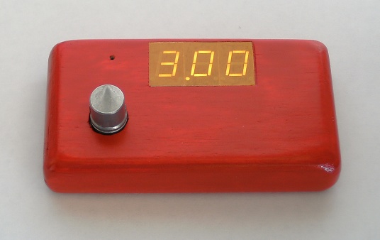
Short-time "egg" timer
The software is in firmware/. The entire source is in main.c, but there are more than one version, as the project evolved. Two settings (AVR chip type and clock frequency) are in the makefile. I am using avr-gcc for compiling and avr-dude for flashing, but both in the "Mac OSX flavour" AVR CrossPack and AVRFuses.
The makefile is used only for compiling, as i use "AVRfuses" for programming, so the AVR programming parts herein are broken. Basically the AVR chip "ATtiny2313" and the clock frequency "1 MHz" are defined here.
The software makes some assumptions on the hardware, which should be easy to adapt if your available parts are different:
• The 3 LED displays have left-handed decimal point, which is quite unusual, because i only had displays of this kind.
• They are of common anode type.
• The rotary encoder settles in 1-1 and 0-0 position.
• The buzzer is an intelligent type which buzzes when applied to power.
• Resistors are calculated for 3.6V but will work for 5V too.
The software implements a 1000 Hz timer interrupt, which is used to multiplex the LED digits (obviously at 333.3Hz) and to read and debounce the input switches and to be used as time basefor all timings.
The software runs until there is nothing left to do but wait for the next event. Then it goes to sleep.
When the egg timer is switched off, then the controller is set to deepest sleep mode. In this mode the 100µF capacitor kept the chip alive for more than 20 minutes, so, yes, really, it works and should have no measurable effect on the battery.
Rough description of the version 1 software:
After applying power, the software loops through a digit and buzzer test.
Pressing the button (of the rotary encoder) enters sleep mode.
Pressing the button again awakes the controller and enters time setting mode.
Turning left increases the time, turning right decreases the time. Granularity of the time steps increases with the currently selected duration. Maximum time is 99 minutes + 59 seconds. Minimum time is 5 seconds. Rotating beyond 0 seconds turns the egg timer off.
Pressing the buttin starts the timer. The first 5 seconds it shows the remaining time blinking, then only a moving dot (using the decimal point) and for the last 5 seconds it blinks the remaining time again. Then it buzzes a calculated number of times (the longer the duration was, the more often) and goes to sleep.
Pressing the button while the timer is running, shows the remaining time for 5 seconds.
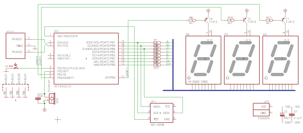
The circuit diagram and board are designed in EagleCAD (english page), which is free for non-commercial use and up to 1/2-sized Euro boards (80x100mm).
The circuit and board sources can be found in the archive below. Higher resolution images and PDFs of the plots are in XL/.
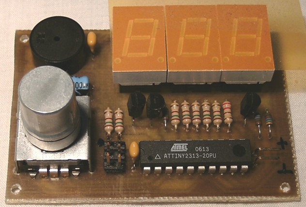
The circuit is very straight forward. The LED displays in my egg timer are of common anode type with left-handed decimal point. The ATtiny drives the segment lines directly and the common anode via a transistor. The resistor values might need adjustment to result in a bright display, based on the actually available specimen and used voltage.
The ATtiny2313 is directly soldered into the PCB and therefore i have included a 6-pin programming header.
Disconnect the battery before applying power over the programming header!
The buzzer i used is a "CPM 121" (from Reichelt Elektronik), a buzzer with integrated electronics which runs at 3-15V. I have measured it with approx. 3.5mA, so well in range of the driving capacity of the ATtiny port pins.
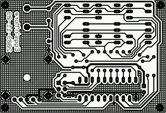
Plot of the printed circuit board
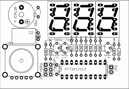
Component placement
The ATtiny is directly soldered onto the board, whereas the displays are plug into sockets. This makes them rise high enough to peek through the front plate.
For space reduction, i have used one AA-sized 3.6V lithium battery. The case consists of a front plate from 4mm plywood and the sides are cut from one part of timber batten.
I have used a print of the component placement plot to make exact cut-outs for the knob, display and buzzer.
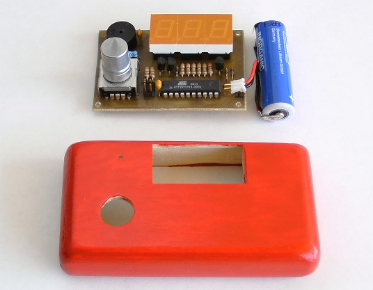
Wooden case, populated board and lithium battery
| Name | Letzte Änderung | Länge | |||
|---|---|---|---|---|---|
| EggTimer based Oven timer built by Puiu Bercioiu/ | 2019-08-20 05:21 | 4 | |||
| firmware/ | 2019-08-20 05:21 | 12 | |||
| OSX-AVR-Tools/ | 2020-08-29 15:16 | 4 | |||
| timer.xcodeproj/ | 2019-08-20 05:21 | 5 | |||
| XL/ | 2019-08-20 05:21 | 5 | |||
| ATtiny2313 - AVR 8-bit, 2k Flash.pdf | 2006-10-16 10:54 | 1700809 | |||
|
case + electronics.jpg size: 536 × 417 |
2009-11-29 11:27 | 59698 | ||
|
circuit diagram.png size: 1016 × 447 |
2009-11-29 11:31 | 30292 | ||
|
component placement.png size: 536 × 369 |
2009-11-12 18:24 | 14037 | ||
|
egg timer.jpg size: 536 × 338 |
2009-11-29 11:30 | 55160 | ||
|
PCB.png size: 530 × 361 |
2009-11-12 18:22 | 14709 | ||
 |
populated board.jpg size: 632 × 427 |
2009-11-12 18:06 | 94110 | ||
| timer.brd | 2009-11-09 19:08 | 28152 | |||
| timer.sch | 2009-11-09 18:57 | 38641 |
powered by vipsi - your friendly VIP Script Interpreter
![]()
![]()