
|
/Develop/Hardware/K1-Bus IO Boards/Audio/ |
| k1.spdns.de / Develop / Hardware / K1-Bus IO Boards / Audio / |
|
|
/Develop/Hardware/K1-Bus IO Boards/Audio/ |
| k1.spdns.de / Develop / Hardware / K1-Bus IO Boards / Audio / |
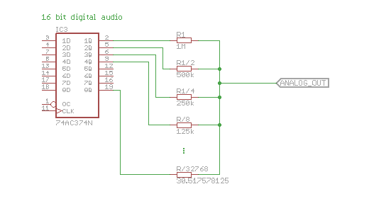 For the duration of each sample you store the sample in a 16 bit (or two 8 bit) data latch. The outputs are connected via well calculated resistors, which reflect the 'weight' of the bits. In this simplified circuit the output swings from 0V to Vcc.
If we start with 1MΩ for bit 0 then we'll end at 1MΩ/2^15 = 30.517578125Ω for bit 15. The accuracy for each resistor has to increase from 50% for R0 to 50%/2^15 for R15: 0.0015%.
Approx. 5 resistors can be used with 1% out of the box, then ~ 5 will need an adjustable trimmer and the remainder even two, … and you'll have to adjust them, else you get the typical errors of such networks: increasing a sample from e.g. 0b00011111 to 0b00100000 may not increase the output but decrease it, just because the single resistor switched in for 0b00100000 has too high an error. The resistor network must be carefully adjusted by hand, due to the "high" tolerances of the resistors.
 Adjusting the weight of each bit in the time domain, which is highly accurate because oscillators don't tend to change their frequency very fast, in general eliminates the need for adjustment.
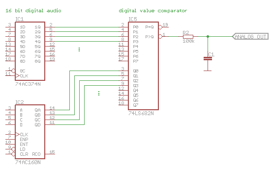
The sample is stored in a 16 bit register and a 16 bit counter is incremented from 0 to 2^16-1 during the time for one sample. An output comparator indicates whether the sample value is reached or not. Depending on this the output is switched to 0 or Vcc.
There are two problems with this design:
First, the output switches from min. to max. value at the sample frequency, a very loud signal which must be carefully eliminated by filters.
Second, the required counter frequency is a little bit high: At a sampling frequency of 44.1 kHz we need to count from 0 to 2^16 for each sample: 44100 x 65536 = 2,890,137,600; roughly 3 GHz. Out of domain…
My 3rd idea was to somehow use only the difference to the last sample. When i examined how to compress audio data some time ago, i found that only storing the difference from sample to sample could save some bits, but after all the effect was too little and i stopped there. But when i thought over an audio D/A converter the idea came back to mind.
First step is to find the maximum expectable difference between two samples in a real-world audio signal.
Example 1: a 20 Hz sine tune at 0dB, where 0dB refers to the maximum achievable signal amplitude of 0 .. 2^16-1 or ±2^15.
One period is 1/20s and at 44.1 kHz this is 2205 samples. At 0-crossing we have an increase of 1:1 if we normalize the period to 2π and the signal amplitude to 1. So, if we increase the signal by (2^15/1) / (2205/2π) per sample in the 0-crossing point, then this corresponds to a sine with ±2^15 amplitude. This makes ~ 93.4 per sample. Or in short:
max.delta/sample = 2^15 / f(sample) * f(signal) * 2π = 2^15 / 44100 * 20 * 2π = 93.4.
This is the loudest possible sine tune and a delta of ±93 looks "tiny". :-)
But bad things happen at night: let's increase the frequency to 200 Hz:
max.delta/sample = 2^15 / f(sample) * f(signal) * 2π = 2^15 / 44100 * 200 * 2π = 934.
Ugh ugh…
And of course at 20 kHz:
max.delta/sample = 2^15 / f(sample) * f(signal) * 2π = 2^15 / 44100 * 20000 * 2π = 93400.
Uh, that's even a lot more than the maximum elongation. Actually we can't sample 2 points near 0-crossing for such a high-frequency signal. ;-)
But the world is not only bad, there is hope: Real-world audio does not contain such loud high frequencies. Looking at your speaker (real speakers, not the PMPO thing attached to your PC) you know, that the high frequency speaker is much smaller than the bass. Most power in a real-world audio signal is in the bass, much less in the high frequencies. The question is: how much less? I could do a scan over a couple of audio files, but that would require some programming work, instead i found this nice chart at esp/Australia when working on my audio stereo Amp:
.png) It shows the maximum amplitude of a radio program after recording for some hours, so including music and speech.
It shows the maximum amplitude of a radio program after recording for some hours, so including music and speech.
First thing to be aware is, that there is a steep cut at approx. 15 kHz and a peak at 19 kHz: this is artifical and done for technical reasons in a stereo radio signal. So ignore this, better extrapolate the signal from 15 kHz to the right.
As you can see, the maximum signal amplitude rolls off for high frequencies. Let's pick some corner points:
-3 dB at 80 Hz (loudest)
-6 dB at 600 Hz
-10 dB at 3 kHz
-20 dB at 5 kHz
-30 dB at 12 kHz
-40 dB at 18 kHz
I deliberately picked the values at -10/20/30/40 dB because they are easier to calculate. So let's start with the question:
Part One: What is a bel? --> See Wikipedia.
One bel measures a power increase by 10.
After that a bel is divided logarithmically into 10 steps, the dezibels.
So 10 dB simply mean 10-fold power. Note: power, not voltage. Since a voltage increase over a fixed resistor also increases the current, and the power is the product of voltage and current, a voltage increase by SQRT(10) equals a power increase by 10 or 10 db. Or a voltage increase by 10 equals a power increase by 100 or 20 db. That's why i looked for the easy dB numbers…
Back to the power vs. frequency chart. Let's calculate the the max.delta/sample for the above picked frequencies:
80  Hz @  -3 dB: 1/SQRT(2)    * 2^15 / 44100 *    80 * 2π ~ 264
600 Hz @  -6 dB: 1/2          * 2^15 / 44100 *   600 * 2π ~ 1867
3  kHz @ -10 dB: 1/SQRT(10)   * 2^15 / 44100 *  3000 * 2π = 4429
5  kHz @ -20 dB: 1/10         * 2^15 / 44100 *  5000 * 2π = 2334
12 kHz @ -30 dB: 1/SQRT(1000) * 2^15 / 44100 * 12000 * 2π = 1771
18 kHz @ -40 dB: 1/100        * 2^15 / 44100 * 18000 * 2π = 840
So let's make a note of this: Maximum expectable ∆ signal is ±4500. Roughly.
Just for curiosity:
3 kHz @ -10 dB: 1/SQRT(10) * 2^15 / 48000 * 3000 * 2π = 4069.
Actually not for curiosity. First 4069 gives very nice 12 bit. And second it's hard to find a quartz with a frequency of 44.1kHz * N, while 12 MHz * N are standard.
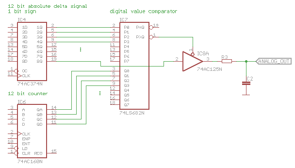 An incremental delta circuit basically looks like this. At a first glance this is very similar to the PWM circuit, which required a clock frequency of 3 GHz. But here we have only a 12 bit counter and not 16 bit, which results in a 16-fold lower clock frequency:
f(clock) = f(sample) * 2^12
= 48000 * 4096
= 196,608,000 ~ 200 MHz.
Hmm… better, but yet not easy. Main problem: The clock itself. Browsing through my local suppliers i only find quartz oscillators up to 80 MHz. And in my spare parts as well.
How does it work?
The output capacitor stores the "current value". While enabled, the 3state driver adds charge to it or remove charge from it, depending on the sign of the delta signal. The voltage at the capacitor will rise and fall appropriately. The amount of charge added depends on the time, the voltage difference and the resistor. Time is what is controlled by the comparator.
The voltage difference accros the resistor should be const, but isn't, unless the voltage difference is high compared to the signal swing or you use a stabilized current source instead. My idea is to make the voltage swing little compared to 5V, ±100mV will probably be a good value. Subsequent amplification of the signal is required anyway.
A nice side effect of this design is, that it can be overdriven vastly without the typical digital hard clipping. E.g. if you add and add charge the voltage can grow widely beyond it's nominal value of e.g. 100mV. 10-fold overcharge, which is +20dB, results in a voltage of 1V. Quite ok. The degradation is only, that 'adding' charge add's less (due to less voltage across the resistor when pulled to Vcc) while subtracting charge subtracts more (due to higher voltage across the resistor when pulled to GND), if elongated so far. This results in minimal distortion but will, on the long run, auto-center the voltage.
Another nice side effect of an incremental delta converter is, that the transition between samples is slowly and much less high frequency noise is present in the output signal.
~200 MHz are way out. ~100 MHz might work. We must reduce the counter frequency, and therefore the counter depth. The options i see are:
1: The simplest solution: this will work without distortion except for very loud signals in the 3 kHz range. The driver software could simply limit the delta values it send's to the hardware to ±2^11. The auto-center feature of the circuit would prevent a run-off of the center voltage of the output signal. I'm not shure how much audible this distortion would be in a real-world loud music part.
2: This will effectively reduce the D/A converter to 15 bit.
3: The bypass resistor would need to be of 12 bit accuracy (compared to the main charging resistor) or it will not improve the 15 bit "main" DAC to 16 bit but make the signal worse. But it has only to be adjusted once per channel, as opposed to the resistor network solution.
4: This considerably increases the head count on the PCB. The resistors of the two outputs must be matched with 12 bit precision. One counter must count one clock cycle longer if the least bit is set. Not so easy.
5: This only reduces the accuracy of the D/A converter to 15 bit if a high delta value must be added. Eventually the voltages must be calibrated with 12 bit precision, which may be easy if the 1/2 voltage is generated from a PWM signal.
6: The "half bit" must only be added if the LSB of the 12 bit value is set. It could be time adjusted (1/2 clock cycle) or by using a double value resistor.
Starting from idea 3 i came to another design idea:
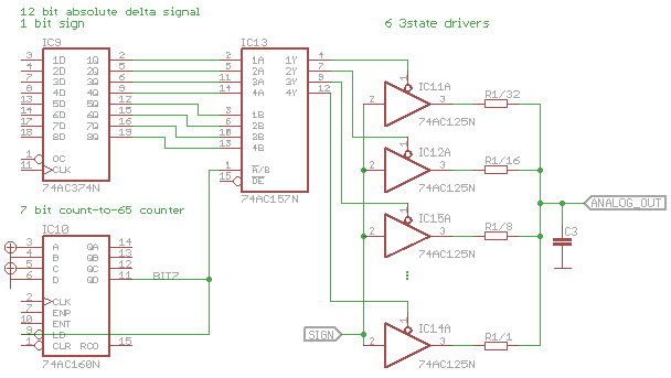 The 12 delta.sample bits are split into lower and upper half of 6 bits each. The idea is to multiplex between these two halfes and the ratio has to be 2^6/1 = 64/1. So the upper bits are forwarded for 64 cycles and the lower bits for 1 cycle. The counter has to be wired up to count up to 64+1 = 65 and deliver the select signal for the 74157 or similar.
Basically this mixes in a resistor network. While the resistor network had to be adjusted up to 1/2^16 precision for 16 inputs, here up to 1/2^12 for only 6 inputs is required. The advantage compared to the initial incremental delta method is, that we only need a clock frequency of 44.1kHz * 65 = 2.8665 MHz, which is very low. The exact value will not be available, so we'll work with a customary sampling frequency, or we could insert dummy clock cycles, during which no charge is added/removed from the output capacitor. Also, the oscillator frequency may be a multiple of the base frequency, then the counter would loop several times per sample.
And, to come back to the original resistor network, we could just do a plain incremental delta with 12 bit resistor network. This eliminated the counters and multiplexer, but we'd need to adjust 12 resistors instead of 6, and adjusting them would be more complicate.
| Name | Letzte Änderung | Länge | |||
|---|---|---|---|---|---|
|
max. vol. vs. frequ. (Radio).png size: 640 × 294 |
2014-08-31 10:42 | 26820 | ||
| v0.1.s#1 | 2014-09-01 15:00 | 121241 | |||
| v0.1.sch | 2014-09-01 15:41 | 115355 | |||
| Hi-Fi RIAA Phono Preamp | 100 |
powered by vipsi - your friendly VIP Script Interpreter
![]()
![]()