
|
/Vintage/Sinclair/Other Inventions/Neoteric 60 Stereo Amplifier/ |
| k1.spdns.de / Vintage / Sinclair / Other Inventions / Neoteric 60 Stereo Amplifier / |
|
|
/Vintage/Sinclair/Other Inventions/Neoteric 60 Stereo Amplifier/ |
| k1.spdns.de / Vintage / Sinclair / Other Inventions / Neoteric 60 Stereo Amplifier / |
Information is based on Richard Torrens www.torrens.org.uk, who worked for Sinclair Radionics from 1964 to 1975.
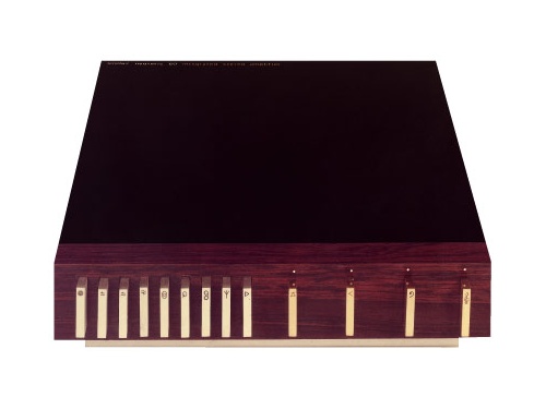
The Sinclair Neoteric 60 was launched at the Audio Fair at the Hotel Russell, London in April 1968 and was sold until 1973.
Concept and supervision: Clive Sinclair
Circuit design: Martin Wilcox
Artistic design: Ian Sinclair
The initial internal design was done by Martin Wilcox himself: it had sub-modules with connecting wires. It was a complete failure being very difficult to manufacture and almost impossible to repair. It also had a steel cover which hummed in the magnetic field of the mains transformer. This version is best forgotten and eventually none of them still exist.
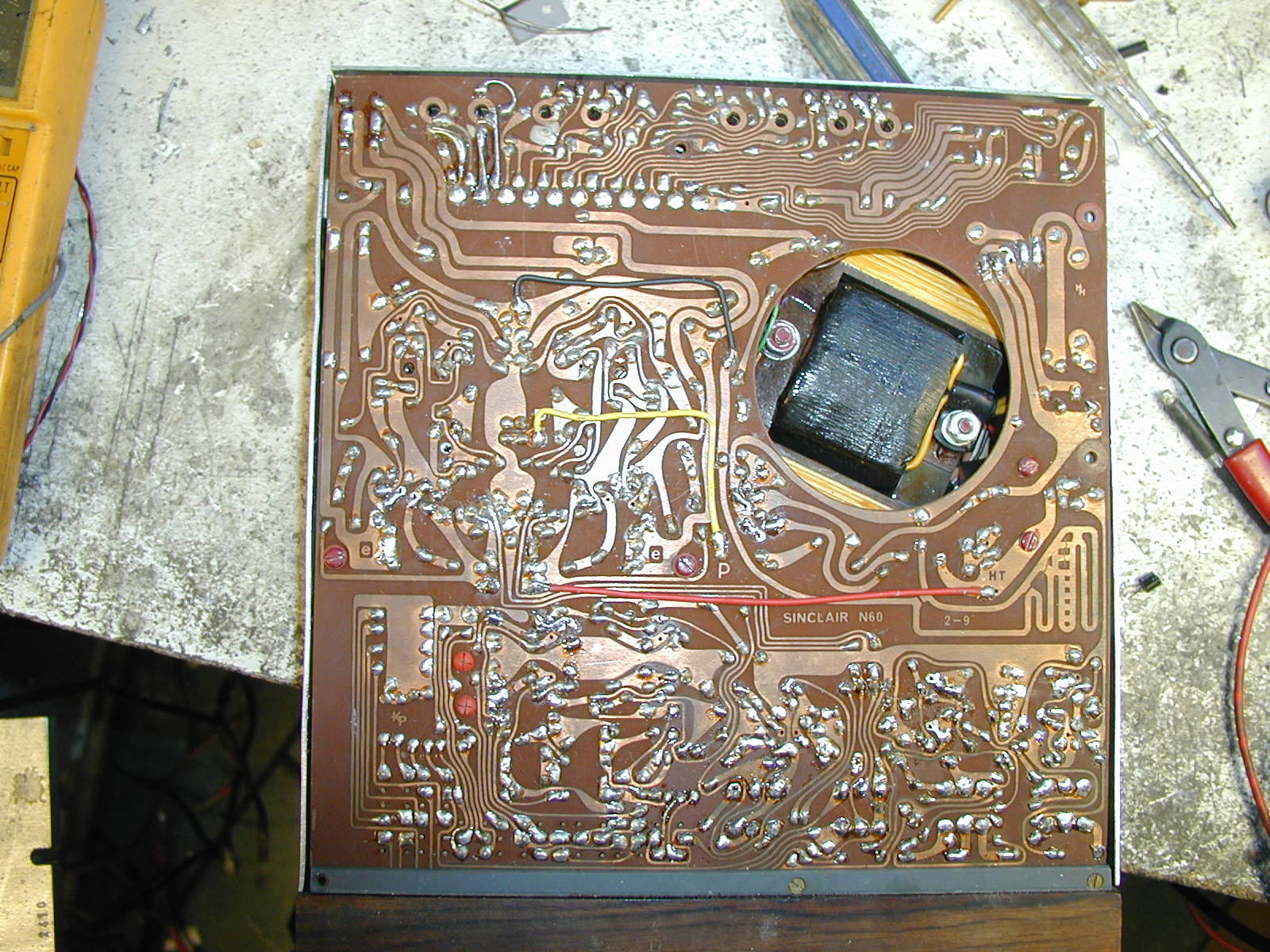
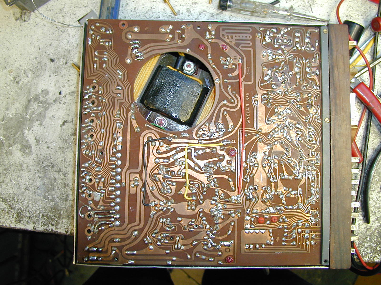
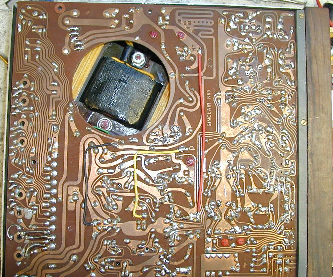
Board re-layout by Keith Pauley (see KP logo on the circuit board) so that everything was on one circuit board. It was easier to produce and much easier to repair. Chassis and cover were both aluminium, removing the magnetic hum. Some problem with rejected rosewood fronts, as the wood tended to break in the wrong place.
Circuit board, metalwork and assembly by Harvey Hall Electronics Ltd. in Thetford.
from Richard Torrens
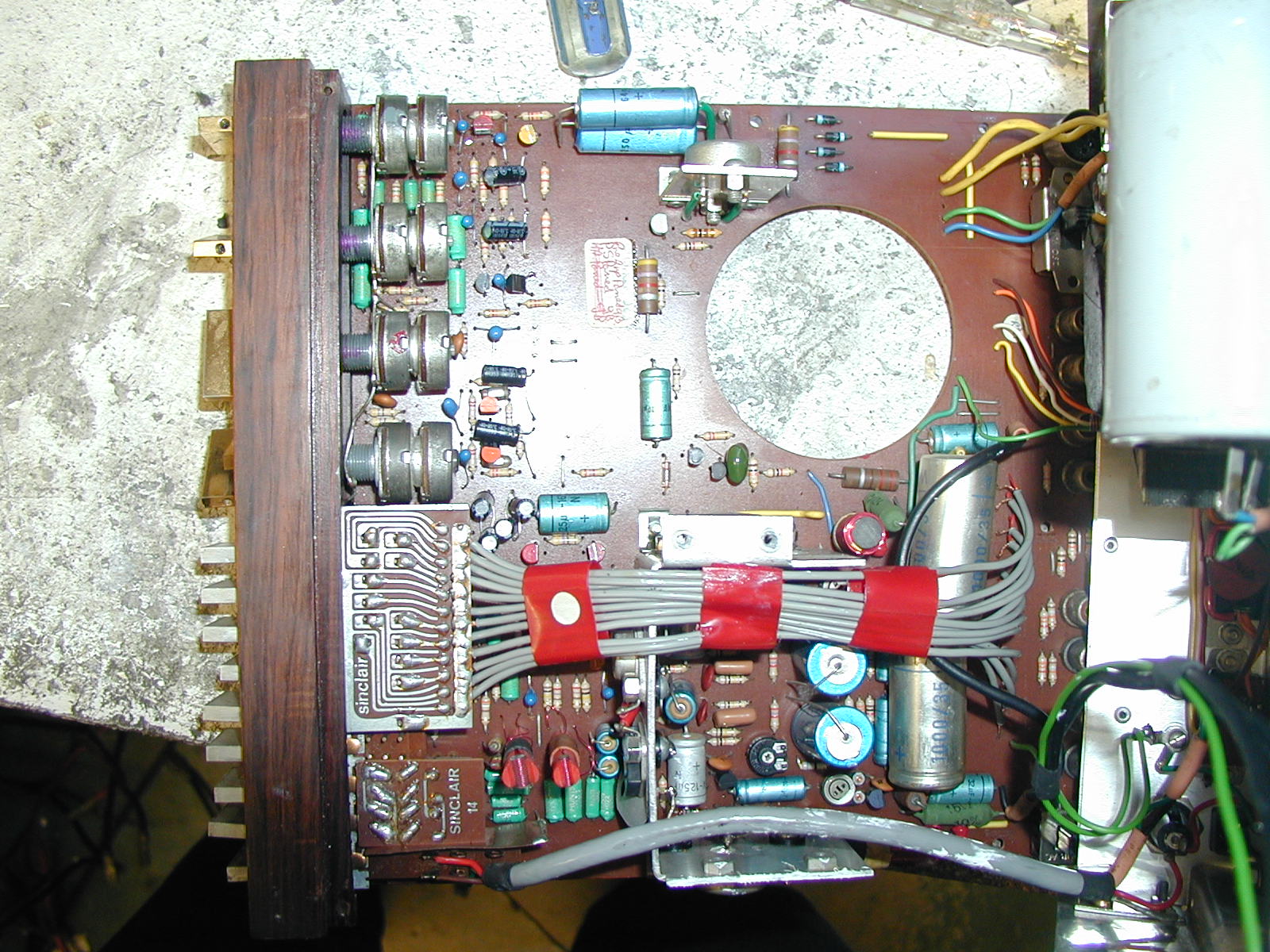
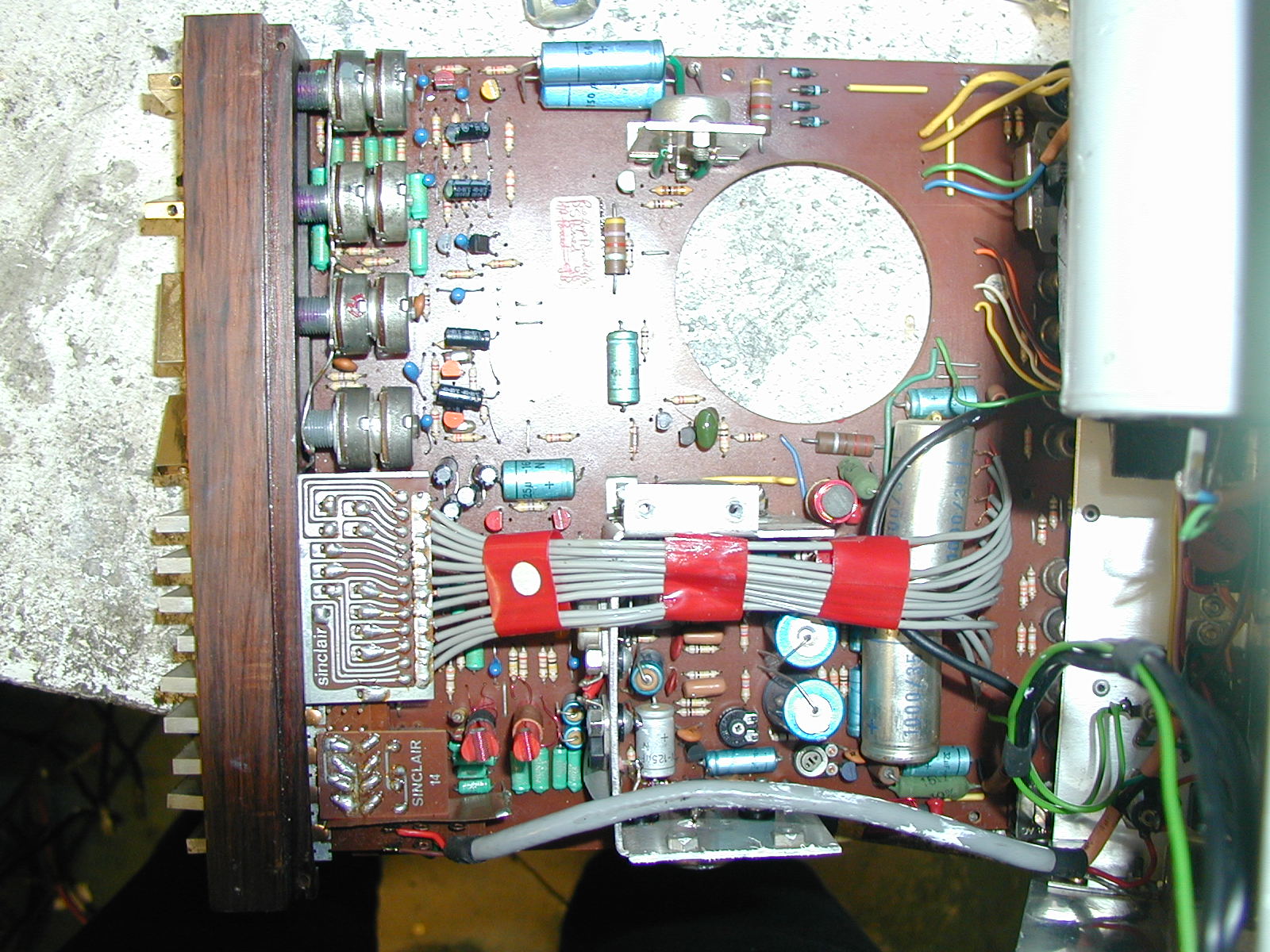
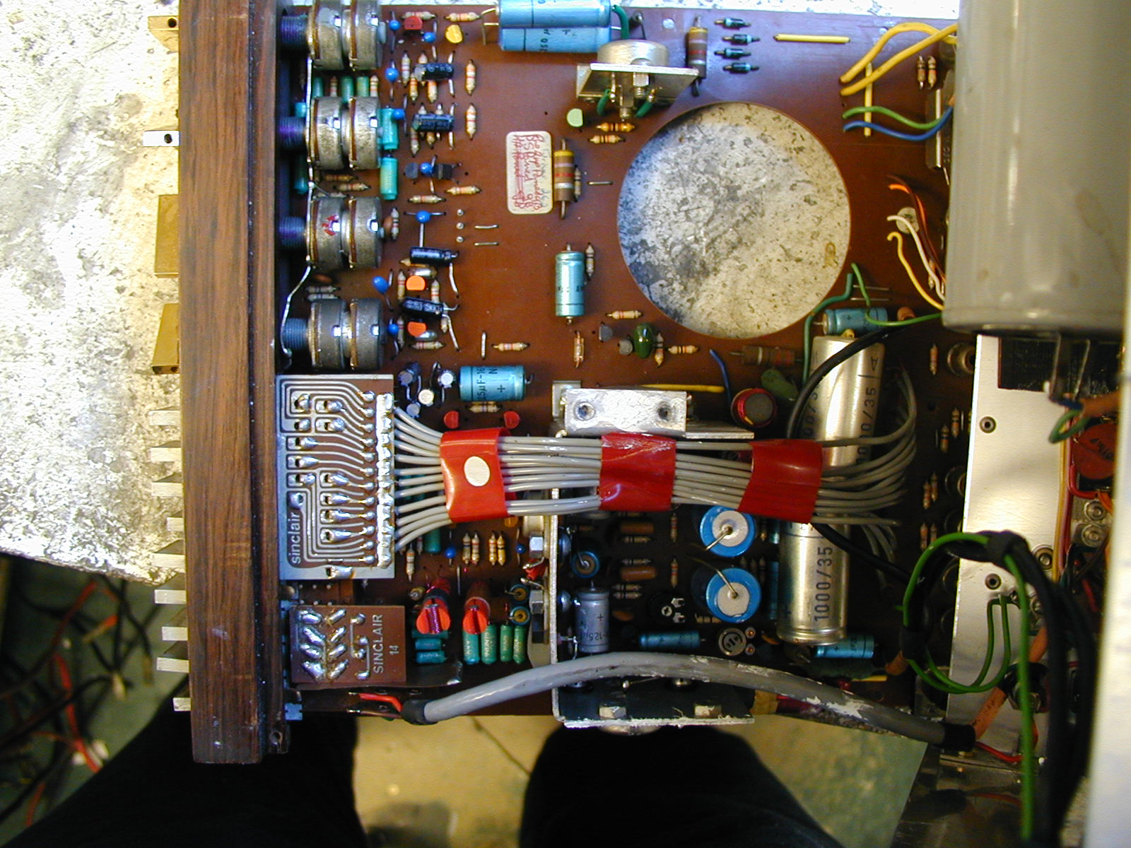
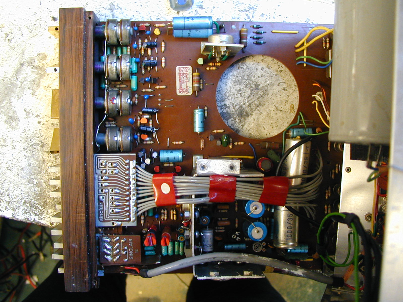
Components that have almost certainly failed will be the electrolytic capacitors. These dry out with time and the Neoteric dates from around 1970. So if in doubt it's best to replace all electrolytics. This includes C44, the 2500µF 63V main reservoir capacitor, and C41L/R - the speaker capacitors, 100µF 25V.
The transistors that are stressed most are the power transistors. The PNP power transistors were Germanium ones, type AL102, made by ATES who later combined with SGS. These are still available. The two NPN Power transistors were silicon, NKT0033, manufactured by Newmarket Transistors. The nearest readily available replacement is likely to be 2N3054, which is the same TO66 case and a near enough equivalent.
The board was of SRBP (simple resin bonded paper) so is fragile. Inserting a plug into the board-mounted phono sockets could cause the tracks to break away from the board. The photographs of the Neoteric show these tracks, where they have been repaired.
Just behind the push switches, visible in the photos, are two red plastic pieces, with crosses cut into them. These are the hum-bucking coils.
The mains transformer is in relatively close proximity to the inputs and, although it is separated as much as space allows, some mains hum is induced in input wiring. These two items hold coils which are rotated with the plastic piece, to minimise mains hum. In practise this works well, though the pedantic, using an oscilloscope, may notice that, because the magnetic field from the transformer is distorted, the coils can be set to minimise either 100Hz hum or 50Hz hum, but not both at the same time. So the adjustment is best done by listening closely to the loudspeakers and tuning for least audible hum.
| Name | Letzte Änderung | Länge | |||
|---|---|---|---|---|---|
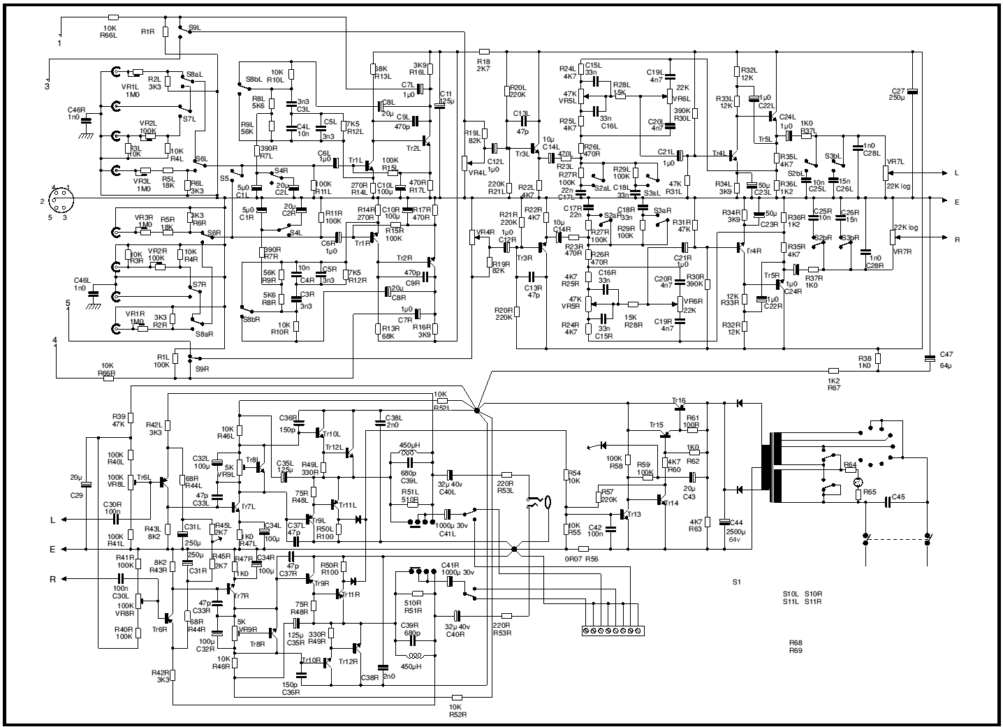 |
cct.png size: 1436 × 1041 |
2016-09-28 17:14 | 68895 | ||
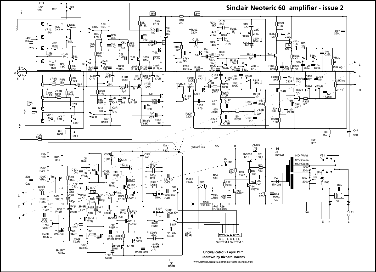 |
circuit.png size: 1571 × 1136 |
2016-09-28 17:40 | 168243 | ||
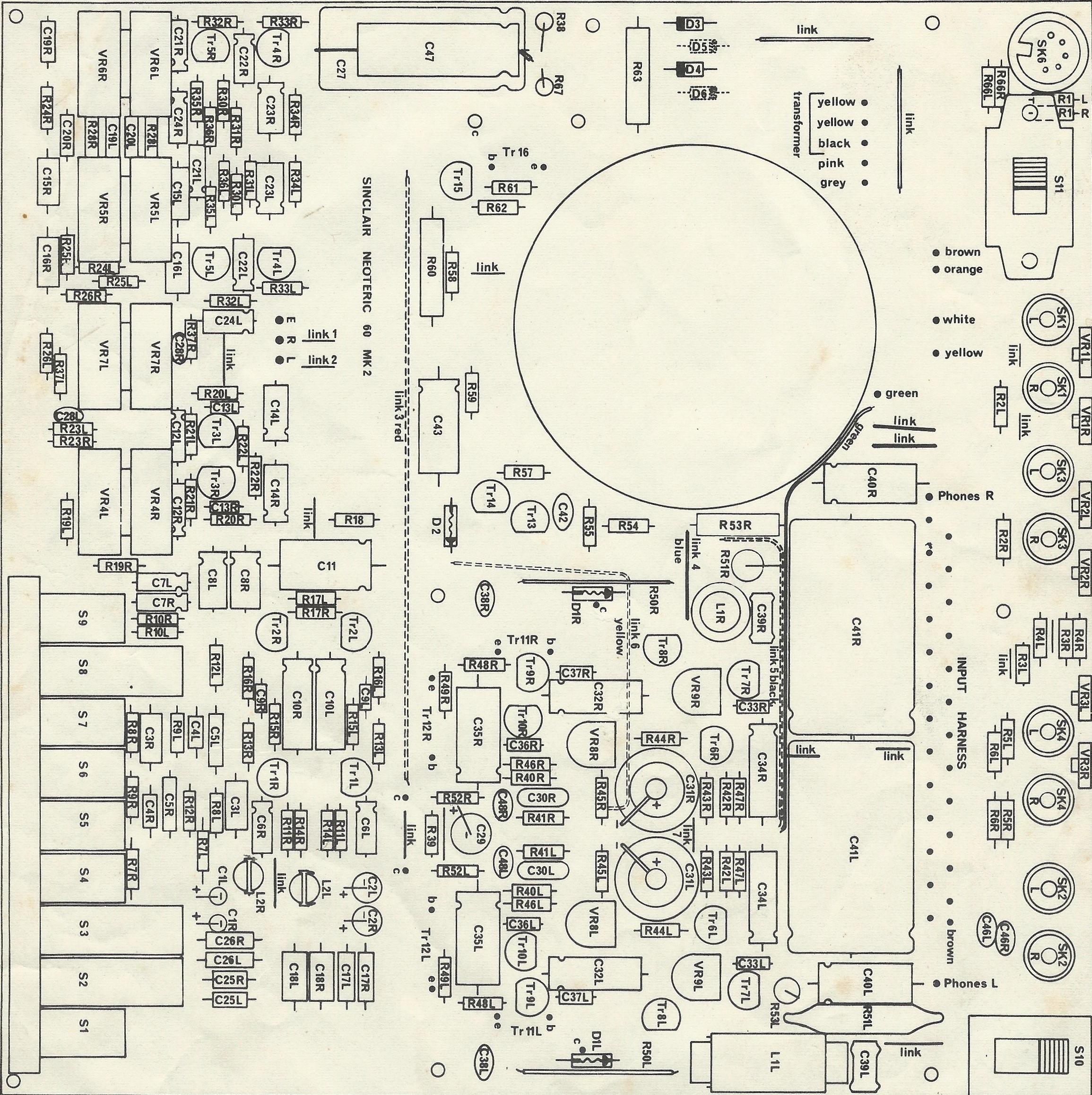 |
component placing.jpg size: 2310 × 2316 |
2016-09-28 17:43 | 956260 | ||
.jpg) |
Neoteric 60 (1968).jpg size: 400 × 300 |
2008-07-22 13:41 | 19273 | ||
 |
Neoteric.jpg size: 500 × 375 |
2016-09-28 18:14 | 26783 | ||
| Neoteric60_cct.pdf | 2014-08-24 19:26 | 112773 | |||
 |
PB130012.JPG size: 1600 × 1200 |
2016-09-28 17:46 | 426630 | ||
 |
PB130013.JPG size: 1600 × 1200 |
2016-09-28 17:46 | 428225 | ||
 |
PB130014.JPG size: 1600 × 1200 |
2016-09-28 17:47 | 407387 | ||
 |
PB130015.JPG size: 1600 × 1200 |
2016-09-28 17:47 | 404214 | ||
 |
PB130016.JPG size: 1600 × 1200 |
2016-09-28 17:46 | 396032 | ||
 |
PB130017.JPG size: 1600 × 1200 |
2016-09-28 17:46 | 403824 | ||
 |
pcb.jpg size: 1168 × 973 |
2016-09-28 17:17 | 283672 | ||
| Richard-Torrens-Electronics-Neoteric | 108 |
powered by vipsi - your friendly VIP Script Interpreter
![]()
![]()