 zxsp currently supports the video mode of the original machines. Enhanced modes for the To Do: other:other machines are in the pipe.
zxsp reproduces Video outputvideo output of the 16 kB machines up to Amstrad's model +2 with high precision. Actually i currently know of no scene demo which does not work as expected. This applies to both in-screen Done: 2000 – 0.1.8 and 0.2.2and border effects. If you find any differences send me email Done: 2000 – 0.1.8 and 0.2.2and Snapshotssnapshot please.
Video outputVideo output uses OpenGL Done: 2000 – 0.1.8 and 0.2.2and hopefully hardware scaling. The video zoom adapts to the window size Done: 2000 – 0.1.8 and 0.2.2and is truncated to integer values, the padding around the screen displays border. So just resize the window to get different magnification Done: 2000 – 0.1.8 and 0.2.2and different amount of border.
Video frames are updated 50 times a second - if possible. Depending on the amount of action in the screen, your computer's power Done: 2000 – 0.1.8 and 0.2.2and the amount of open instances Done: 2000 – 0.1.8 and 0.2.2and To Do: other:other programs frames are dropped.
ULA control panel
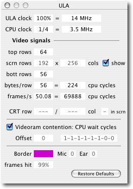 In the windows menu you find a panel for the ULA, which in essence forms a CRTC (cathode ray tube controller) plus the Keyboardkeyboard Done: 2000 – 0.1.8 and 0.2.2and ear/mic i/o port. Besides those ports it has no real Debugger: Registersregisters, but i have added some so we can play around a little, investigating why a certain demo behaves wrong or the like. If you want to cancel editing in a field, just enter empty data.
ULA clock
All timings in a Modifier keys: ZX SpectrumZX Spectrum are derived from a single crystal, which is predivided by the ula Done: 2000 – 0.1.8 and 0.2.2and fed namely to the cpu. You can throttle or overdrive the whole machine by adjusting the ula input Registers: Clockclock. Either you enter a percentage value in the left input field or the frequency in the right field. In the frequency field you can also add units like MHz or kHz. Accordingly the ULA control panel: CPU clockcpu clock Done: 2000 – 0.1.8 and 0.2.2and screen timings vary.
Though the AY Soundsound chip Registers: Clockclock is also produced by the ula, this fact is ignored Done: 2000 – 0.1.8 and 0.2.2and the AY Soundsound chip Registers: Clockclock is set in the Sound: AY control panelAY panel individually, because it's unlikely that you want to change the pitch of the Soundsound if you increase or decrease the machine's speed.
The running program can't detect that you have changed the ula input Registers: Clockclock, because the amount of ULA control panel: CPU clockcpu clock Video signals: Frames per secondcycles per interrupt is not changed. As the interrupt frequency goes up or down, the Keyboardkeyboard repeat varies accordingly.
There are menu shortcuts for some commonly used speed settings in Menu > Tape recorder: OptionsOptions > Machine Throttle/Overdrive.
You cannot speed-up Snapshots: .TAPtape loading this way, because the Tape recordertape recorder is a separate unit which feeds Soundsound into the audio buffers for all open machine instances.
The ULA control panel: ULA clockula clock is currently limited to 1 Hz Done: 2000 – 0.1.8 and 0.2.2and 100 MHz respectively. As there are also limits on the cpu frequency setting, the ULA control panel: ULA clockula clock typically can't be lowered below 4 Hz or rised above 80 MHz. These limits are applied for your security, so that you can't block your entire Mac too easily.
CPU clock
The ULA control panel: CPU clockcpu clock is derived from the ula's input Registers: Clockclock by a 1/4 predivider. You can change the predivider from the Modifier keys: ZX SpectrumZX Spectrum standard value of 1/4 to 1/1, 1/2 or 1/8. Accordingly the cpu executes more or less Video signals: Frames per secondcycles per interrupt.
A machine code program can detect this change; intentionally or by crashing. As the interrupt frequency is not altered, Keyboardkeyboard repeat or the like is not affected.
There are some menu shortcuts for commonly used speed settings in Menu > Tape recorder: OptionsOptions > ULA control panel: CPU clockCpu Clock Predivider.
You can also enter a new value into the frequency field. As this does not affect the cpu predivider the overall speed of the machine is changed, just as setting the ula input Registers: Clockclock. All these fields change accordingly.
The ULA control panel: CPU clockcpu clock is currently limited to 1 Hz Done: 2000 – 0.1.8 and 0.2.2and 20 MHz respectively. This is for your security, so that you can't block your entire Mac too easily.
Video signals
All fields here are for experimenting with the Video outputvideo output. Changes here change the total amount of cpu Video signals: Frames per secondcycles per interrupt Done: 2000 – 0.1.8 and 0.2.2and can be detected by the running program. Entered values are pinned to reasonable limits Done: 2000 – 0.1.8 and 0.2.2and forced to valid multiples of what-ever-applies.
Top rows
Change the amount of border lines above the usable screen.
Screen rows
You cannot change the amount of rows per screen or pixels per row, because too much is hard coded here. But you can switch off the screen, so that the display only shows the border as it would appear underneath the screen pixels. This is similar to the ZX 81's fast mode, but does not disable the related cpu wait states. It may be useful to check Done: 2000 – 0.1.8 and 0.2.2and adjust the timing of the demo you just decided to write.
Bottom rows
Change the amount of border lines below the usable screen.
Bytes per row
Changes the amount of linear bytes read by the ula to form one scan line. Typically this is 56 or 57, depending on the model. The first 32 bytes come from the screen pixels Done: 2000 – 0.1.8 and 0.2.2and are read in blocks of 2 bytes (plus another 2 bytes for attributes, which are not counted here. therefore the term 'linear' bytes) The remainder is border. Somewhere in the middle of the border range is the horizontal beam flyback, so that the last bytes from a scan line are actually displayed as left-side border of the next scan line on the TV screen.
Equally you can change the amount of Registers: CPU cyclecpu cycles per scanline, which derives from the bytes per scan line read by the ula Done: 2000 – 0.1.8 and 0.2.2and the ULA control panel: CPU clockcpu clock predivider.
Frames per second
Another chance not only to see another interesting value but to change the overall speed of the machine. ula Done: 2000 – 0.1.8 and 0.2.2and ULA control panel: CPU clockcpu clock are adjusted accordingly, while all To Do: other:other counter settings which affected the overall Video signals: Frames per secondframes per second are kept.
The second field displays the amount of cpu Video signals: Frames per secondcycles per interrupt, which is a very important value when you write your own demo.
CRT row, col
When you throttle down the machine heavily to watch how a demo or similar draws to screen, or when the cpu is paused, then these fields are activated Done: 2000 – 0.1.8 and 0.2.2and show the current row Done: 2000 – 0.1.8 and 0.2.2and column of the video beam. Also a Registers: Flagsflag indicates, whether it is currently within the inner screen area Done: 2000 – 0.1.8 and 0.2.2and the cpu will suffer from lots of wait states if it accesses the video page right now. Also at some point a video beam indicator is inserted into the screen image to aid you pushing your demo's timing to the limit.
Video ram contention
Here you can switch off any wait states for the contended MMU registers for the +128K / +2: RAM $8000
MMU registers for the +128K / +2: RAM $4000
MMU registers for the +3 / +2A: RAM $8000
MMU registers for the +3 / +2A: RAM $4000ram pages.
The two input fields are still disfunct. (as of Done: 2008-05-26 - Version 0.7.2
Done: 2007-07-28 - Version 0.7.1
Done: 2007-05-13 - Version 0.7.0
Done: 2007-05-01 - Version 0.6.7.1
Done: 2007-03-29 - Version 0.6.6
Done: 2006-11-18 - Version 0.6.5
Done: 2005-01-16 - Version 0.6.2
Done: 2004-11-26 - Version 0.6.1version 0.6.3)
Border, Mic, Ear
These fields show the current state of the only actually existing ula register.
Frame hits
Shows how many frames out of 100 were actually drawn in the last two seconds.
Restore Defaults
Your last resort if you have messed up too many settings. ;-)
MMU registers for the +128K / +2
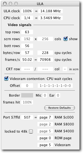 If you set the machine to Modifier keys: ZX SpectrumZX Spectrum +128K, +2 or similar, then the ULA panel expands Done: 2000 – 0.1.8 and 0.2.2and reveals more display fileds for the page control register, MMU registers for the +128K / +2: Port $7FFD
MMU registers for the +3 / +2A: Port $7FFD
MMU registers for the +3 / +2A: Port $1FFDport $7FFD. This port cannot be read by the running programme; but now, you can. ;-)
The MMU allows you to select any of 8 MMU registers for the +128K / +2: RAM $8000
MMU registers for the +128K / +2: RAM $4000
MMU registers for the +3 / +2A: RAM $8000
MMU registers for the +3 / +2A: RAM $4000Ram pages to be mapped into the upper address $C000 … $FFF of the CPU, to select the MMU registers for the +128K / +2: Videoram
MMU registers for the +3 / +2A: Videoramvideoram from page 5 or 7, the Snapshots: .ROM
MMU registers for the +128K / +2: ROM $0000Rom page for the lower address range $0000 … $3FFF of the CPU Done: 2000 – 0.1.8 and 0.2.2and to lock the whole machine into 48K mode for ever.
Port $7FFD
You can edit the port byte, but you should know when Done: 2000 – 0.1.8 and 0.2.2and with which value, or your Specci crashes immediately. All To Do: other:other text fields show the derived states of individual MMU functions:
RAM $c000
Select which MMU registers for the +128K / +2: RAM $8000
MMU registers for the +128K / +2: RAM $4000
MMU registers for the +3 / +2A: RAM $8000
MMU registers for the +3 / +2A: RAM $4000Ram page is paged in at the upper address range $C000 … $FFFF. This can be any of the 8 MMU registers for the +128K / +2: RAM $8000
MMU registers for the +128K / +2: RAM $4000
MMU registers for the +3 / +2A: RAM $8000
MMU registers for the +3 / +2A: RAM $4000Ram pages 0 to 7.
RAM $8000
This MMU registers for the +128K / +2: RAM $8000
MMU registers for the +128K / +2: RAM $4000
MMU registers for the +3 / +2A: RAM $8000
MMU registers for the +3 / +2A: RAM $4000Ram page can't be changed in the +128K.
RAM $4000
This MMU registers for the +128K / +2: RAM $8000
MMU registers for the +128K / +2: RAM $4000
MMU registers for the +3 / +2A: RAM $8000
MMU registers for the +3 / +2A: RAM $4000Ram page too can't be changed in the +128K.
ROM $0000
This selects which Snapshots: .ROM
MMU registers for the +128K / +2: ROM $0000Rom page to page in in the lower address range $000 … $3FFF. This can be either Snapshots: .ROM
MMU registers for the +128K / +2: ROM $0000Rom page 0, which is the boot Snapshots: .ROM
MMU registers for the +128K / +2: ROM $0000Rom page Done: 2000 – 0.1.8 and 0.2.2and contains the additional stuff for the +128K, or Snapshots: .ROM
MMU registers for the +128K / +2: ROM $0000Rom page 1, which contains the 48K model's Snapshots: .ROM
MMU registers for the +128K / +2: ROM $0000Rom.
Videoram
Select one of the two possible MMU registers for the +128K / +2: RAM $8000
MMU registers for the +128K / +2: RAM $4000
MMU registers for the +3 / +2A: RAM $8000
MMU registers for the +3 / +2A: RAM $4000Ram pages for the screen display: page 5 (standard) or page 7.
Locked to 48k
The Mmu can be locked to 100% compatible 48K mode. Normally when this bit is set by the programme, it can not be changed back except if you reset the machine.
MMU registers for the +3 / +2A
 If you set the machine to Modifier keys: ZX SpectrumZX Spectrum +2A, +3 or similar, then the ULA panel expands even more Done: 2000 – 0.1.8 and 0.2.2and reveals display fileds for the page control register, MMU registers for the +128K / +2: Port $7FFD
MMU registers for the +3 / +2A: Port $7FFD
MMU registers for the +3 / +2A: Port $1FFDport $7FFD Done: 2000 – 0.1.8 and 0.2.2and $1FFD. Both ports cannot be read by the running programme. Major new mode is the 'MMU registers for the +3 / +2A: RAM onlyRam only' mode, as opposed to the standard 'MMU registers for the +3 / +2A: ROM $0000 / RAM $0000Rom+Ram' mode.
Port $7FFD
This is mostly identical to the Tape recorder: Optionsoptions for the +128K / +2, except that the new high bit for the Snapshots: .ROM
MMU registers for the +128K / +2: ROM $0000Rom page selection is stored in MMU registers for the +128K / +2: Port $7FFD
MMU registers for the +3 / +2A: Port $7FFD
MMU registers for the +3 / +2A: Port $1FFDport $1FFD. Remember, the +3 / +2A now have 64 kB (4 pages) of Snapshots: .ROM
MMU registers for the +128K / +2: ROM $0000Rom.
The MMU MMU registers for the +128K / +2: Port $7FFD
MMU registers for the +3 / +2A: Port $7FFD
MMU registers for the +3 / +2A: Port $1FFDport $7FFD allows you to select any of 8 MMU registers for the +128K / +2: RAM $8000
MMU registers for the +128K / +2: RAM $4000
MMU registers for the +3 / +2A: RAM $8000
MMU registers for the +3 / +2A: RAM $4000Ram pages to be mapped into the upper address $C000 … $FFF of the CPU, to select the MMU registers for the +128K / +2: Videoram
MMU registers for the +3 / +2A: Videoramvideoram from page 5 or 7, the Snapshots: .ROM
MMU registers for the +128K / +2: ROM $0000Rom page for the lower address range $0000 … $3FFF of the CPU Done: 2000 – 0.1.8 and 0.2.2and to lock the whole machine into 48K mode for ever.
Port $1FFD
This is the new port, which contains bits to select the new 'MMU registers for the +3 / +2A: RAM onlyRam only' mode, the high bit for Snapshots: .ROM
MMU registers for the +128K / +2: ROM $0000Rom selection, 2 bits to select from 4 layouts for the 'MMU registers for the +3 / +2A: RAM onlyRam only' mode Done: 2000 – 0.1.8 and 0.2.2and bits to set the MMU registers for the +3 / +2A: Printer strobeprinter strobe Done: 2000 – 0.1.8 and 0.2.2and the MMU registers for the +3 / +2A: Disc motordisc motor.
RAM $c000
Select which MMU registers for the +128K / +2: RAM $8000
MMU registers for the +128K / +2: RAM $4000
MMU registers for the +3 / +2A: RAM $8000
MMU registers for the +3 / +2A: RAM $4000Ram page is paged in at the upper address range $C000 … $FFFF. In MMU registers for the +3 / +2A: ROM $0000 / RAM $0000Rom+Ram mode this can be any of the 8 MMU registers for the +128K / +2: RAM $8000
MMU registers for the +128K / +2: RAM $4000
MMU registers for the +3 / +2A: RAM $8000
MMU registers for the +3 / +2A: RAM $4000Ram pages 0 to 7; in Ram-only mode this can be page 3 or 7.
RAM $8000
Select the MMU registers for the +128K / +2: RAM $8000
MMU registers for the +128K / +2: RAM $4000
MMU registers for the +3 / +2A: RAM $8000
MMU registers for the +3 / +2A: RAM $4000Ram page which is paged in at $8000 … $BFFF. In MMU registers for the +3 / +2A: ROM $0000 / RAM $0000Rom+Ram mode this can only be page 2, in Ram-only mode this can be page 2 or page 6.
RAM $4000
Select the MMU registers for the +128K / +2: RAM $8000
MMU registers for the +128K / +2: RAM $4000
MMU registers for the +3 / +2A: RAM $8000
MMU registers for the +3 / +2A: RAM $4000Ram page which is paged in at $4000 … $7FFF. In MMU registers for the +3 / +2A: ROM $0000 / RAM $0000Rom+Ram mode this can only be page 5, in Ram-only mode this can be page 1, 5 or page 7.
ROM $0000 / RAM $0000
In MMU registers for the +3 / +2A: ROM $0000 / RAM $0000Rom+Ram mode, this selects which Snapshots: .ROM
MMU registers for the +128K / +2: ROM $0000Rom page to page in in the lower address range $000 … $3FFF. This can be either Snapshots: .ROM
MMU registers for the +128K / +2: ROM $0000Rom page 0, which is the boot Snapshots: .ROM
MMU registers for the +128K / +2: ROM $0000Rom page Done: 2000 – 0.1.8 and 0.2.2and contains the additional stuff for the +128K, or Snapshots: .ROM
MMU registers for the +128K / +2: ROM $0000Rom page 3, which contains the 48K model's Snapshots: .ROM
MMU registers for the +128K / +2: ROM $0000Rom, or page 1 or page 2, which contain the editor Done: 2000 – 0.1.8 and 0.2.2and DOS or stuff. In 'Ram-only' mode this selects the MMU registers for the +128K / +2: RAM $8000
MMU registers for the +128K / +2: RAM $4000
MMU registers for the +3 / +2A: RAM $8000
MMU registers for the +3 / +2A: RAM $4000Ram page which is paged in at $0000 … $3FFF, which can be page 0 or page 4.
Videoram
Select one of the two possible MMU registers for the +128K / +2: RAM $8000
MMU registers for the +128K / +2: RAM $4000
MMU registers for the +3 / +2A: RAM $8000
MMU registers for the +3 / +2A: RAM $4000Ram pages for the screen display: page 5 (standard) or page 7.
Locked to 48k
The Mmu can be locked to 100% compatible 48K mode. Normally when this bit is set by the programme, it can not be changed back except if you reset the machine.
RAM only
Select the new 'MMU registers for the +3 / +2A: RAM onlyRam only' mode or the old 'MMU registers for the +3 / +2A: ROM $0000 / RAM $0000Rom+Ram' mode.
In the standard 'MMU registers for the +3 / +2A: ROM $0000 / RAM $0000Rom+Ram' mode, the Snapshots: .ROM
MMU registers for the +128K / +2: ROM $0000Rom Done: 2000 – 0.1.8 and 0.2.2and MMU registers for the +128K / +2: RAM $8000
MMU registers for the +128K / +2: RAM $4000
MMU registers for the +3 / +2A: RAM $8000
MMU registers for the +3 / +2A: RAM $4000Ram paging is controlled by the $7FFD port as in the +128K or +2.
In 'MMU registers for the +3 / +2A: RAM onlyRam only' mode, all memory pages are set to MMU registers for the +128K / +2: RAM $8000
MMU registers for the +128K / +2: RAM $4000
MMU registers for the +3 / +2A: RAM $8000
MMU registers for the +3 / +2A: RAM $4000Ram pages Done: 2000 – 0.1.8 and 0.2.2and the selection from 4 possible layouts is taken from two bits in the $1FFD port:
address      mode 0  mode 2  mode 4  mode 6
-------------------------------------------
$C000…$FFFF  page 3  page 7  page 3  page 3
$8000…$BFFF  page 2  page 6  page 6  page 6
$4000…$7FFF  page 1  page 5  page 5  page 7
$0000…$3FFF  page 0  page 4  page 4  page 4
Disc motor
start/stop floppy MMU registers for the +3 / +2A: Disc motordisc motor. Not yet supported. [2007-03]
Printer strobe
set/reset printer port strobe line. Not yet supported. [2007-03]