A Miniature UHF Video Transmitter - Using the ASTEC UM1233
Please Note :
It is technically illegal to use this transmitter in the United Kingdom as a
license cannot be obtained for it's use.
Although the
output power is extremely low & the chances of detection are very
slight indeed, you use it
entirely at
your own risk. It is not however illegal to build or own in any
way.
A manual-tune TV set is required for use with this transmitter
A manual-tune TV, as the name suggests, is a TV
that can be physically tuned by hand (manually).
Usually, these TV's
have individual 'presets' or thumbwheels for tuning each channel under a
front or side flap on the TV set. Some older B/W and and most very small
portable colour sets, have a single large knob for tuning.
TV's sets with + /
-
/ and 'store/memory' buttons for tuning, will
NOT work with this transmitter. With many modern
sets,
all the tuning is done via the remote-control handset. These
"auto-search" TV's, even the ones with a "fine tune"
facility, will
not pick up the signal from this modifided modulator.
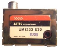
The Astec UM1233 UHF Modulator
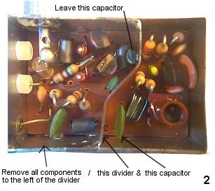
Step 1 - Removing Unwanted Components
Remove the covers from the modulator and remove all
the components to the left of the divider, leaving only the single
small capacitor shown. Then remove the divider itself by unsoldering
the points where it is attached to the case and
the 3 pins that pass
through the PCB. Finally, remove the large capacitor shown in photo
2.
This leaves you with just the circuit of the tuned UHF Colpits oscillator.
If you want to build a half-size
version of the transmitter, continue to Step 2a,
otherwise proceed to Step 2b
Step 2a - Halfing the size of the Modulator
Using a ruler, draw 2 lines exactly centrally on both
sides of the modulator housing, and then place the modulator
in a
vice, the lines you have drawn, facing upwards. Using a junior hacksaw,
cut PART WAY through the case on both
sides. Turn the modulator around
in the vice so the the PCB is facing upwards. Aligning the hacksaw with
the cuts
already made in the case sides, cut right through the PCB,
continuing until the modulator is separated into 2 pieces.
One half of the modulator has 2 wires poking out of
one end - desolder these wires from the PCB. Remove the wire
that
passes through the white plastic insulator. The other wire (which appears
to be fixed to the case) actually passes
Unsolder the PCB at the 3 points it is attached to the metal casing - discard the PCB.
Place the remaing U-shaped piece of metal in a vice and using a hacksaw, cut through the corners to leave you with
just the rectangular 'endplate'. File off any sharp edges and (using pieces of 'blu-tack'), hold it in place as shown in
photo 3. You can then solder the top and bottom corners of the plate to the casing, securing it in place (photo 4).
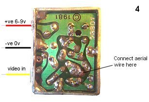
Step 2b - Wiring
Strip 1 inch of insulation from both ends of a short length thin YELLOW, BLACK and RED solid-core wire.
Pass the YELLOW wire through the top hole in
the white plastic insulator. Solder this wire (Video In) to the location
on the PCB shown in picture 3. Pass the BLACK wire through the
centre hole, and solder this directly to the case
internally - this
provides the (-VE) connection to the transmitter. Finally, the 'Feedthough
Capacitor' has to be heated up
with a soldering iron before you can
pass the RED (+VE) wire through it. Solder this wire to the position shown
in photo 3.
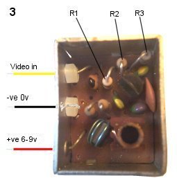
Step 3 - Component Modifications
Change R1 to 3.3K * / Change R2 to 10R / Change R3 to 220R**
* Depending on the video output level of your
camera module, the value of this resistor can be changed.
A lower value, eg 2.2K, will give a higher video level
(more contrast) - A higher value, eg 4.7k will give a lower video
level and will therefore lower the level of contrast in
the picture.
** The value of this resistor alters the power
output of the transmitter. Any value from 180R to 330R will work. The
lower
the value of the resistor, the higher the output
power. The higher the output power, the shorter the battery life
!
Step 4 -
Making The Aerial & Finishing off
Cut a piece of stiff insulated wire to a length
of 25.5cm. This will form your aerial. Solder one end the wire to the PCB
track shown in Picture 4. Make sure the wire is
pointing vertically (straight up).
Check for any
'high-points' and solder bridges or bad joints on the PCB -
remedy these as nessecary.
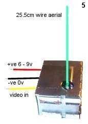
Take the cover
plate with the hole in it and cut it exactly in half - a pair of
heavy-duty scissors will do the job.
Refit the covers
to your transmitter - the aerial wire passes through the hole in the plate
(photo 5).
Step 5 - Initial Testing & Setup
Apply a power source to the transmitter (any
voltage beween 6V & 9V DC) - a PP3 battery will work
well.
Using a MANUAL-TUNE TV *,
attached to a SET-TOP INDOOR AERIAL, adjust the TV tuning until you get a
blank, black (or dark-grey) picture.
A signal should be obtained somewhere between UHF channels 30 -
40.
When you disconnect the power to the transmitter,
the signal should
dissapear.
* Please read the text
at the top of the page for more information about manual-tune
TV's.
Disconnect the power to the transmitter before proceeding with the steps below !
Step 6 - Connecting a standard composite video source to the input of the transmitter
Digital Cameras / VCR's / Satelite Receivers
All digital cameras have a socket marked 'video
out' - If the socket is not a standard yellow RCA or 'phono' socket,
a suitable lead should be supplied with the
camera. If you want to use a VCR or Satelite Receiver as a
video source,
a SCART lead can be purchased, terminated
with 3 coloured phono plugs. The yellow plug is the 'video out'
source.
On the SCART plug will be a switch.
Be sure to set the switch to the 'OUT' position.
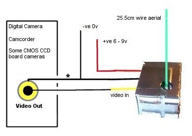
IMPORTANT
* Depending on the signal configuration of the
video source used, this transmitter may be found to
work
better if the GROUND (screening) of the
video source lead is connected to the
+VE POSITIVE
SUPPLY
of the transmitter, rather than the usual of the
-VE Connection, as shown in
the above picture above.
Try both
configurations to establish which method produces the best and the most
stable picture for you !
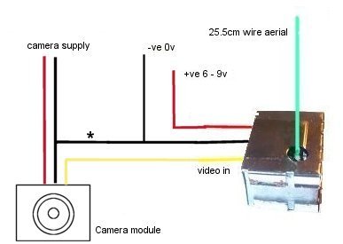
CCD / CMOS Board Cameras
Most Board Cameras have just 3 wires attatched - RED (+ve) - BLACK (-ve) and YELLOW (video out)
Connect the camera module as shown below. The
camera will need it's own supply - usually 12V
DC.
Some cameras will work down to 6V even though
their stated operating voltage is 12V - do try it.
If
this is the case, then your transmitter & camera can share the same
6-9V supply - easy !
Step 7 - Getting a Good Picture
With the video input connected in the
appropriate diagram shown above, reconnect power to the transmitter and
slowly retune your TV 'back and forth' until a good
clear picture is obtained.
TROUBLESHOOTING GUIDE
" I can't get any signal on my TV- no blank black (or dark-grey) picture whatsoever"
1 Are you using a manual-tune TV ?
- please read the text at the top of this page for more
information..
2 Have you got a set-top indoor aerial attached to the TV
?
3 Have you connected the power-supply wires to the transmitter
correctly ?
4 Is the aerial on the transmitter soldered to the correct
track on the PCB & is it vertical ?
5 Have you
remembered to change the value of the resistors & are they fitted
correctly ?
6 Is your battery OK ?
If the answer
to all 6 questions is "YES" then you have a fault with your transmitter -
check your work very carefully.
Look for bad solder joints / solder
bridges between tracks and general 'short circuits' on the
PCB.
"I get a vague picture - rolling / not much colour / almost looks embossed or inverted"
That fact that you are getting a picture of any sort, proves that the transmitter is working.
1 Have you readjusted the tuning slightly on
your 'manual-tune' TV ?
2 Is the 'video input'
connection wired correctly ? (both wires MUST be connected - see diagrams
above)
3 Have you fitted the correct values for all the
resistors ? - recheck them carefully.
4 Read the section
"IMPORTANT" in Step 6 and try the
alternative video wiring method.
If the answer to all 4 questions is "YES" and you still can't get a good picture, try a different video source.
If you continue to experience difficulties,
email me at richard@timetec.freeserve.co.uk
I
will try to help you resolve any problems you may have.
Transmitter Range
The range of the transmitter is very dependent
on conditions and the supply voltage used. Brick walls and
other
solid structures will reduce
the level of the signal, limiting the range of the
transmitter considerably.
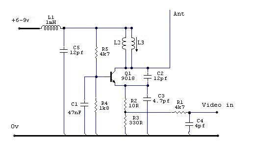
The Circuit Diagram