| |
Back | Last edited: 2005-11-28 kio |


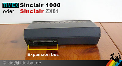
On the rear side is the ZX80-compatible expansion port.
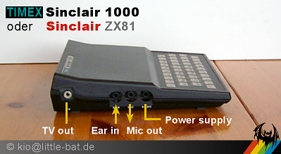
All other connectors are at the left side of the body.
This is a Cinch socket which should be connected with the supplied cord to the TV antenna input. The signal of the ZX81 should be on UHF channel 36.
This is the audio input for loading programmes from a tape recorder. It is a 3.5 mm mono jack. It can be connected to the Ear or Line out output of the tape recorder or HiFi equipment. All connectors are not properly surrounded by chassis plastic and you can easily insert a plug between two sockets or in the wrong socket. So be careful.
The sequence of sockets has been changed from the ZX80 to ZX81: For the ZX80 it was Mic - Ear - Power, now for the ZX81 it is Ear - Mic - Power.
This is the audio output for saving programmes and data to a tape recorder. This is a 3.5 mm mono jack too. It can be connected to the Mic or Line in input of the tape recorder or HiFi equipment.
This is the connection for the power supply unit. Again, this is a 3.5 mm mono jack, like the plugs for audio in and out. Be careful not to insert the power plug into the wrong socket!
The PSU delivers unregulated, nominal 9 Volts DC. The tension without load is about 14 Volts. Center pin is +9V, shaft is Gnd.
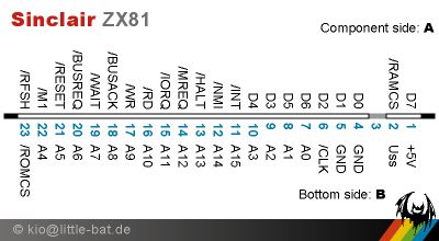
The expansion bus offers a direct connection to many Z80 CPU signals. It is intended to connect RAM extensions and the Sinclair ZX printer. The ZX80 and most/all clones used the same expansion port. The following chart shows the connector layout of the expansion port.

Expansion port connector layout of the ZX81
Uss is the +9V from the power connector.
Page source: The Sinclair ZX Archive <k1.spdns.de>
copyright & courtesy of kio@little-bat.de
May be copied, but keep this note and send mail with link.